Vehicle Interior. Yaris. Ncp93, 131
Seat Belt. Yaris. Ncp93, 131
Seat Belt Warning System (For Sedan) -- Terminals Of Ecu |
| COMBINATION METER ASSEMBLY |
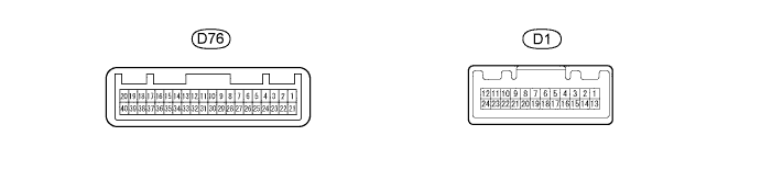
Disconnect the D1 combination meter assembly connector.
Measure the voltage and resistance of the wire harness side connector.
If the result is not as specified, there may be a malfunction in the wire harness.Symbols (Terminal No.) Wiring Color Terminal Description Condition Specified Condition D1-1 - Body ground B - Body ground Ignition switch signal Ignition switch OFF → ON Below 1 V → 11 to 14 V D1-2 - Body ground L - Body ground Battery Always 11 to 14 V D1-24 - Body ground BR - Body ground Ground Always Below 1 Ω Reconnect the combination meter assembly connector.
Measure the voltage of the wire harness side connector.
If the result is not as specified, the combination meter may have a malfunction.Symbols (Terminal No.) Wiring Color Terminal Description Condition Specified Condition D1-20 - Body ground G - Body ground CAN communication line Ignition switch ON Pulse generation D1-21 - Body ground W - Body ground CAN communication line Ignition switch ON Pulse generation D76-9 - Body ground BE - Body ground Seat belt warning light signal (Front passenger side) Ignition switch ON
Front passenger seat is occupied and its seat belt is unfastenedAlternating between 11 to 14 V and below 1 V D76-9 - Body ground BE - Body ground Seat belt warning light signal (Front passenger side) Ignition switch ON
Front passenger seat is occupied and its seat belt is fastenedBelow 1 V
| CENTER AIRBAG SENSOR ASSEMBLY |
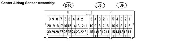
| Terminal No. | Terminal Symbol | Destination |
| D16-13 | CANH | CAN communication line |
| D16-21 | IG2 | IGN fuse |
| D16-22 | CANL | CAN communication line |
| D16-25 | E1 | Ground |
| D16-26 | E2 | Ground |
| J8-11 | DBE+ | Front seat inner belt assembly LH |
| J8-12 | DBE- | Front seat inner belt assembly LH |
| J9-12 | FSP+ | Occupant Classification ECU |
| J9-13 | FSP- | Occupant Classification ECU |
| OCCUPANT CLASSIFICATION ECU |

Disconnect the J24 occupant classification ECU connector.
Measure the voltage and resistance of the wire harness side connector.
If the result is not as specified, there may be a malfunction in the wire harness.Symbols (Terminal No.) Wiring Color Terminal Description Condition Specified Condition J24-7 (IG) - J24-3 (GND) BE - W-B Power source (IG2 Fuse) Ignition switch OFF Below 1 V J24-7 (IG) - J24-3 (GND) BE - W-B Power source (IG2 Fuse) Ignition switch ON 11 to 14 V J24-1 (+B) - Body ground V - Body ground Power source (ECU-B Fuse) Always 11 to 14 V J24-3 (GND) - Body ground W-B - Body ground Ground Always Below 1 Ω Reconnect the occupant classification ECU connector.
Measure the voltage of the connector.
If the result is not as specified, the combination meter may have a malfunction.Symbols (Terminal No.) Wiring Color Terminal Description Condition Specified Condition J24-9 (BSW) - J24-5 (BGND) BE - P Passenger side buckle switch line Buckle switch ON
Buckle switch OFFPulse generation J24-8 (FSR+) - J24-4 (FSR-) GR - Y Center airbag sensor assembly communication line Ignition switch ON Pulse generation