Drivetrain. Yaris. Ncp93, 131
U340E Automatic Transmission Transaxle. Yaris. Ncp93, 131
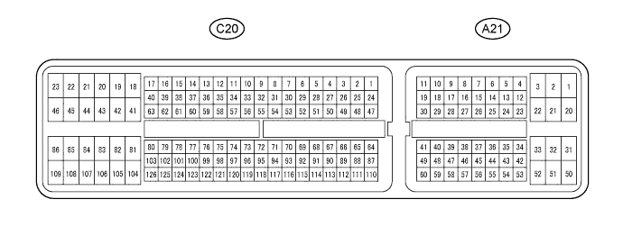
Automatic Transaxle System (For Sedan) -- Terminals Of Ecm |
| ECM |
- HINT:
- Each ECM terminal's standard voltage is shown in the table below.
- In the table, first follow the information under "Condition". Look under "Terminal No. (Symbol)" for the terminals to be inspected. The standard voltage between the terminals is shown under "Specific Condition".
- Use the illustration above as a reference for the ECM terminals.
| Terminal No. (Symbol) | Wiring Color | Terminal Description | Condition | Specified Condition |
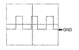
| A21-8 (SPD) - C20-104 (E1) | V - W | Speed signal | Ignition switch ON and driving wheel rotating slowly | Pulse generation (See waveform 1) |
| A21-26 (ODMS) - C20-104 (E1) | BE - W | 3 shift position switch signal | Ignition switch ON and shift lever in 3 | 11 to 14 V |
| Ignition switch ON and shift lever in other than 3 | Below 1 V | |||
| A21-36 (STP) - C20-104 (E1) | G - W | Stop light switch signal | Brake pedal depressed | 7.5 to 14 V |
| Brake pedal released | Below 1.5 V | |||
| C20-52 (STAR) - C20-104 (E1) | BE - W | Park/Neutral position switch signal | Ignition switch ON and shift lever in P or N | Below 2 V |
| Ignition switch ON and shift lever not in P and N | 11 to 14 V | |||
| C20-53 (R) - C20-104 (E1) | R - W | R shift position switch signal | Ignition switch ON and shift lever in R | 11 to 14 V |
| Ignition switch ON and shift lever not in R | Below 1 V | |||
| C20-54 (N) - C20-104 (E1) | SB - W | N shift position switch signal | Ignition switch ON and shift lever in N | 11 to 14 V |
| Ignition switch ON and shift lever not in N | Below 1 V | |||
| C20-55 (2) - C20-104 (E1) | G - W | 2 shift position switch signal | Ignition switch ON and shift lever in 2 | 11 to 14 V |
| Ignition switch ON and shift lever not in 2 | Below 1 V | |||
| C20-56 (D) - C20-104 (E1) | L - W | D shift position switch signal | Ignition switch ON and shift lever in D or 3 | 11 to 14 V |
| Ignition switch ON and shift lever not in D and 3 | Below 1 V | |||
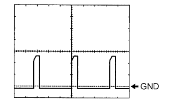
| C20-57 (SLU+) - C20-77 (SLU-) | P - BE | SLU solenoid signal | Engine idling speed | Pulse generation (See waveform 2) |
| C20-72 (THO1) - C20-95 (ETHO) | Y - B | ATF (Automatic Transmission Fluid) temperature sensor signal | ATF temperature: 10°C (50°F) to 145°C (293°F) | 4 to 0 V |
| C20-73 (P) - C20-104 (E1) | R - W | P shift position switch signal | Ignition switch ON and shift lever in P | 11 to 14 V |
| Ignition switch ON and shift lever not in P | Below 1 V | |||
| C20-74 (L) - C20-104 (E1) | V - W | L shift position switch signal | Ignition switch ON and shift lever in L | 11 to 14 V |
| Ignition switch ON and shift lever not in L | Below 1 V | |||
| C20-76 (SLT+) - C20-75 (SLT-) | G - W | SLT solenoid signal | Engine idling speed | Pulse generation |
| C20-78 (S2) - C20-104 (E1) | L - W | S2 solenoid signal | Ignition switch ON | Below 1 V |
| 1st or 4th gear | 11 to 14 V | |||
| 2nd or 3rd gear | Below 1 V | |||
| C20-79 (S1) - C20-104 (E1) | SB - W | S1 solenoid signal | Ignition switch ON | 11 to 14 V |
| 1st or 2nd gear | 11 to 14 V | |||
| 3rd or 4th gear | Below 1 V | |||
| C20-80 (ST) - C20-104 (E1) | GR - W | ST solenoid signal | D position (3rd gear ←→ 4th gear) | Below 1 V ←→ 11 to 14 V |
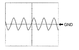
| C20-125 (NT+) - C20-124 (NT-) | B - G | Speed sensor (NT) signal | Engine running | Pulse generation (See waveform 3) |
Waveform 1
Terminal SPD - E1 Tool setting 2 V/DIV, 20 ms/DIV Vehicle conditions Driving at approximately 20 km/h (12 mph) Waveform 2
Terminal SLU+ - SLU- Tool setting 5 V/DIV, 1 ms/DIV Vehicle conditions Engine idling speed Waveform 3
Terminal NT+ - NT- Tool setting 2 V/DIV, 1 ms/DIV Vehicle conditions Driving at approximately 20 km/h (12 mph)
 |
 |
 |