Windshield Glass (For Sedan) -- Installation |
| 1. CLEAN WINDSHIELD GLASS |
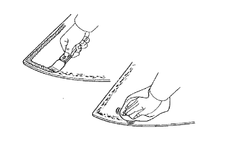 |
Using a scraper, remove the stoppers, dam and adhesive from the windshield glass.
Clean the outer circumference of the windshield glass with a non-residue solvent.
- NOTICE:
- Do not touch the windshield glass surface after cleaning it.
- Even if using a new windshield glass, clean the windshield glass with a non-residue solvent.
| 2. CLEAN VEHICLE BODY |
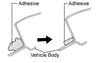 |
Clean and shape the contact surface of the vehicle body.
Using a knife, cut away any rough adhesive on the contact surface of the vehicle body to ensure the appropriate surface shape.
- NOTICE:
- Do not damage the vehicle body.
- HINT:
- Leave as much adhesive on the vehicle body as possible.
Clean the contact surface of the vehicle body with a shop rag or piece of cloth saturated with cleaner.
- HINT:
- Clean the vehicle body even if all the adhesive has been removed.
| 3. INSTALL WINDSHIELD GLASS STOPPER NO. 1 |
 |
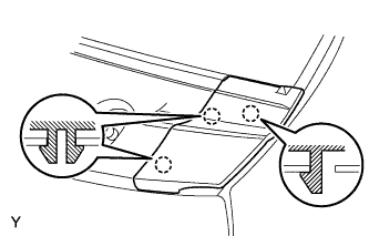
Install 2 new stoppers onto the vehicle body, as shown in the illustration.
| 4. INSTALL WINDSHIELD GLASS STOPPER NO. 2 |
 |
Apply Primer G to the installation parts of the stoppers.
- NOTICE:
- Allow the primer to dry for 3 minutes or more.
- Throw away any leftover Primer G.
- Do not apply too much Primer G.
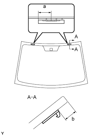
Install 2 new stoppers onto the windshield glass, as shown in the illustration.
- Specification:
Area Measurement a 40 mm (1.57 in.) b 14.5 mm (0.571 in.)
| 5. INSTALL WINDOW GLASS ADHESIVE DAM |
Apply Primer G to the installation part of a new dam, as shown in the illustration.
- NOTICE:
- Allow the primer to dry for 3 minutes or more.
- Throw away any leftover Primer G.
- Do not apply too much Primer G.
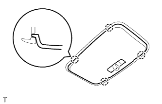
Install the new dam with double-sided tape as shown in the illustration.
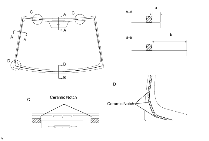
- Specification:
Area Measurement a 7.0 mm (0.276 in.) b 29.4 mm (1.157 in.)
| 6. INSTALL WINDSHIELD GLASS |
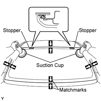
Position the windshield glass.
Using suction cups, place the windshield glass in the correct position.
Check that the entire contact surface of the windshield glass rim is perfectly even.
Place matchmarks on the windshield glass and vehicle body.
- NOTICE:
- Check that the stoppers are correctly attached to the vehicle body.
- HINT:
- When reusing a windshield glass, check and correct the matchmark positions.
Using suction cups, remove the windshield glass.
 |
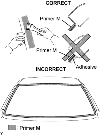
Using a brush, apply Primer M to the exposed part of the vehicle body.
- NOTICE:
- Allow the primer to dry for 3 minutes or more.
- Do not apply Primer M to the adhesive.
- Throw away any leftover Primer M.
- Do not apply too much Primer M.
 |
Using a brush or sponge, apply Primer G to the edge of the windshield glass and the contact surface.
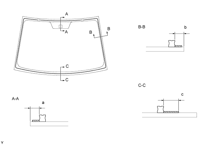
- Specification:
Area Measurement a 7.0 mm (0.276 in.) b 7.0 mm (0.276 in.) c 16 mm (0.630 in.)
- NOTICE:
- Allow the primer to dry for 3 minutes or more.
- Throw away any leftover Primer G.
- Do not apply too much Primer G.
- HINT:
- If Primer G is applied to any areas other than those specified, wipe off the primer with a clean shop rag or piece of cloth before it dries.
Apply adhesive.
- Adhesive:
- Toyota Genuine Windshield Glass Adhesive or the equivalent.
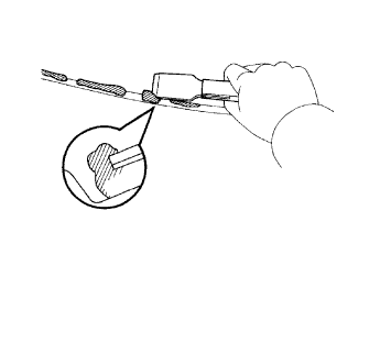
Cut the tip off the cartridge nozzle, as shown in the illustration.
- HINT:
- After cutting off the tip, use all the adhesive within the times indicated in the table below.
- Usage time frame:
Temperature Usage Time Frame 35°C (95°F) 15 minutes 20°C (68°F) 1 hour 40 minutes 5°C (41°F) 8 hours
Load the sealer gun with the cartridge.
Apply adhesive to the windshield glass, as shown in the illustration.
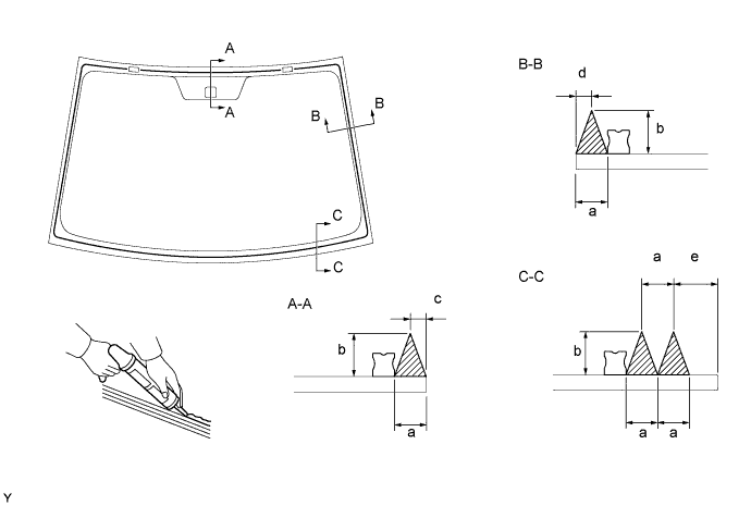
- Specification:
Area Measurement a 8 mm (0.315 in.) b 12 mm (0.472 in.) c 3 mm (0.118 in.) d 3 mm (0.118 in.) e 17.4 mm (0.685 in.)

Install the windshield glass onto the vehicle body.
Using suction cups, position the windshield glass so that the matchmarks are aligned. Gently press it in along the rim.
- NOTICE:
- Allow the primer to dry for 3 minutes or more.
- Check that the stoppers are attached to the vehicle body correctly.
- Check that there is a small gap between the vehicle body and the windshield glass.
Gently press the front surface of the windshield glass to ensure that the windshield glass is securely fitted to the vehicle body.
- NOTICE:
- Open and close the door gently to prevent the window glass from becoming loose due to the air pressure when the door is closed.
Using a scraper, remove any excessive or protruding adhesive.
- HINT:
- Apply adhesive to the windshield glass rim.
- NOTICE:
- Do not drive the vehicle within the time indicated in the table below.
- Minimum time:
Temperature Minimum time prior to driving vehicle 35°C (95°F) 1 hour 30 minutes 20°C (68°F) 5 hours 5°C (41°F) 24 hours
|
| 7. INSTALL WINDSHIELD OUTSIDE MOULDING |
- NOTICE:
- After the installation of the window glass, install the moulding before the adhesive hardens.
Using a brush or sponge, coat the edge of the glass and the contact surface with Primer G.
- NOTICE:
- Allow the primer coating to dry for 3 minutes or more.
- Do not coat the adhesive with Primer G.
- Throw away any leftover Primer G.
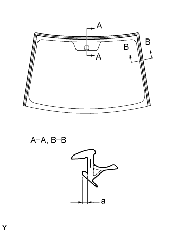 |
Install a new moulding onto the windshield glass, as shown in the illustration.
- Specification:
Area Measurement a 2 mm (0.0787 in.)
- NOTICE:
- Make sure that the moulding is securely installed.
| 8. CHECK FOR LEAKAGE AND REPAIR |
Conduct a leak test by applying water to the adhesive portions after the adhesive has completely hardened.
Seal any leaks with auto glass sealer.
| 9. INSTALL ROOF HEADLINING ASSEMBLY |
| 10. INSTALL INNER REAR VIEW MIRROR |
 |
Slide and install the inner rear view mirror.
Engage the 2 claws and install the cover.
 |
| 11. INSTALL MAP LIGHT ASSEMBLY |
Connect the map light connector.
 |
Engage the 4 claws and install the map light.
 |
| 12. INSTALL ROOM LIGHT ASSEMBLY |
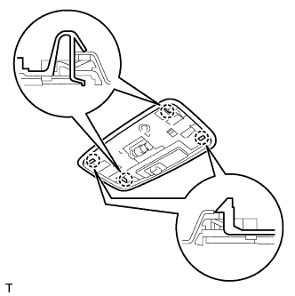
Engage the 4 claws and install the room light switch base.
 |
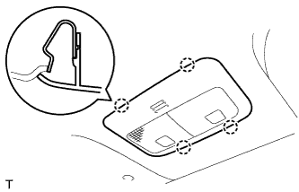
Install the roof wire into the claw of the room light.
Engage the 4 claws and install the room light.
 |
Engage the 2 claws and install the cover.
- HINT:
- Use the same procedure for both sides.
 |
Engage the 4 claws and install the room light lens.
 |
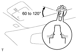
| 13. INSTALL VISOR HOLDER RH |
Engage the 2 claws by turning the visor holder clockwise between 60 to 120° and install the visor holder.
 |
| 14. INSTALL VISOR HOLDER LH |
- HINT:
- Use the same procedure as for the RH side.
| 15. INSTALL VISOR ASSEMBLY RH |
Engage the 2 springs and install the visor.
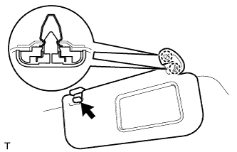 |
Install the visor shaft into the visor holder.
Engage the 4 claws and install a new visor bracket cover.
 |
| 16. INSTALL VISOR ASSEMBLY LH |
- HINT:
- Use the same procedure as for the RH side.
| 17. INSTALL ASSIST GRIP SUB-ASSEMBLY |
 |
- HINT:
- Use the same procedure to install all the assist grips.
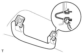
Engage the 2 springs and install the assist grip.
 |
| 18. INSTALL ASSIST GRIP COVER |
 |
- HINT:
- Use the same procedure to install all the assist grip covers.
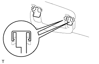
Engage the 2 claws and install the assist grip cover.
 |
| 19. INSTALL FRONT PILLAR GARNISH RH |
w/ Curtain Shield Airbag:
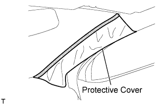
Remove the piece of cloth or nylon.
 |
Install the 3 clamps.
 |
Connect the antenna connector.
w/ Curtain Shield Airbag:
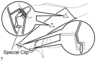
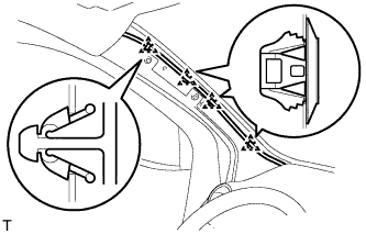
Install 2 new special clips and the clip onto the front pillar garnish.
Engage the 2 clips and the 2 claws and install the front pillar garnish.
 |
w/o Curtain Shield Airbag:
Engage the 2 clips and the 2 claws and install the front pillar garnish.
 |
| 20. INSTALL FRONT PILLAR GARNISH LH |
w/ Curtain Shield Airbag:
Remove the piece of cloth or nylon.
 |
Install the 4 clamps.
 |
w/ Curtain Shield Airbag:
Install 2 new special clips and the clip onto the front pillar garnish.
Engage the 2 clips and the 2 claws and install the front pillar garnish.
 |
w/o Curtain Shield Airbag:
Engage the 2 clips and the 2 claws and install the front pillar garnish.
 |
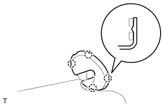
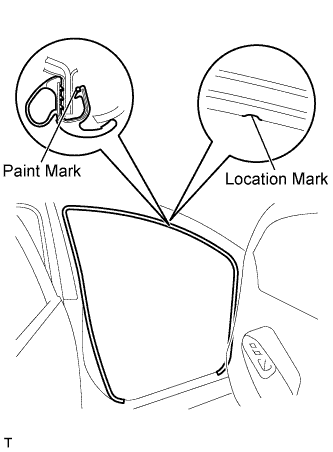
| 21. INSTALL FRONT DOOR OPENING TRIM WEATHERSTRIP RH |
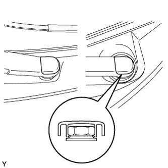
Align the location mark with the paint mark first, and install the front door opening trim weatherstrip, as shown in the illustration.
- Paint mark:
Area Color RH side Blue LH side Pink
 |
| 22. INSTALL FRONT DOOR OPENING TRIM WEATHERSTRIP LH |
- HINT:
- Use the same procedure as for the RH side.
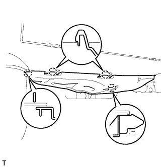
| 23. INSTALL COWL SIDE TRIM BOARD RH |
Engage the stud bolt and the claw and install the cowl side trim board.
 |
| 24. INSTALL COWL SIDE TRIM BOARD LH |
- HINT:
- Use the same procedure as for the RH side.
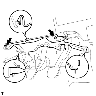
| 25. INSTALL INSTRUMENT PANEL UNDER COVER SUB-ASSEMBLY RH |
Engage the 4 claws and install the instrument panel under cover.
 |
| 26. INSTALL INSTRUMENT PANEL UNDER COVER SUB-ASSEMBLY LH |
Engage the 3 claws and install the instrument panel under cover.
 |
Tighten the 2 screws.
| 27. INSTALL FRONT DOOR SCUFF PLATE RH |
Engage the 11 claws and install the front door scuff plate.
 |
| 28. INSTALL FRONT DOOR SCUFF PLATE LH |
- HINT:
- Use the same procedure as for the RH side.
| 29. INSTALL COWL TOP VENTILATOR LOUVER SUB-ASSEMBLY |
Connect the washer hoses.
 |
Engage the 5 hooks.
Engage the 8 hooks and the 4 claws.
 |
Install the cowl top ventilator louver sub-assembly with the 3 clips.
| 30. INSTALL COWL SIDE VENTILATOR SUB-ASSEMBLY LH |
Engage the 3 claws and install the cowl side ventilator sub-assembly LH.
 |
| 31. INSTALL COWL SIDE VENTILATOR SUB-ASSEMBLY RH |
- HINT:
- Use the same procedure as for the LH side.
| 32. INSTALL FRONT WIPER ARM AND BLADE ASSEMBLY LH |
Scrape any metal powder off the serrated part of the wiper arm with a round file or the equivalent (when reinstalling).
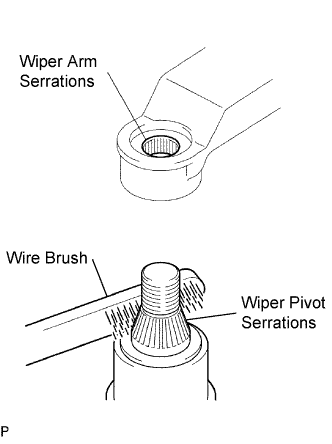 |
Clean the wiper pivot serrations with a wire brush.
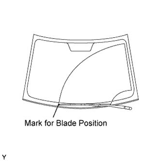
Operate the wiper, then stop the windshield wiper motor in the automatic stop position.
Align the blade tip with the mark on the windshield glass, as shown in the illustration.
 |
Tighten the nut of the front wiper arm.
- Torque:
- 26 N*m{265 kgf*cm, 19 ft.*lbf}
| 33. INSTALL FRONT WIPER ARM AND BLADE ASSEMBLY RH |
Scrape any metal powder off the serrated part of the wiper arm with a round file or the equivalent (when reinstalling).
|
Clean the wiper pivot serrations with a wire brush.
Operate the wiper, then stop the windshield wiper motor in the automatic stop position.
Align the blade tip with the mark on the windshield glass, as shown in the illustration.
 |
Tighten the nut of the front wiper arm.
- Torque:
- 26 N*m{265 kgf*cm, 19 ft.*lbf}
| 34. INSTALL FRONT WIPER ARM HEAD CAP |
Engage the claw and install the 2 front wiper arm head caps.
 |
| 35. CONNECT CABLE TO NEGATIVE BATTERY TERMINAL |
- Torque:
- 5.4 N*m{55 kgf*cm, 48 in.*lbf}
| 36. INSPECT SRS WARNING LIGHT |