Transmission Control Cable (For Hatchback) -- Installation |
| 1. INSTALL TRANSMISSION CONTROL CABLE ASSEMBLY |
Install the transmission control cable assembly with the 3 nuts.
- Torque:
- 5.0 N*m{51 kgf*cm, 44 in.*lbf}
Install the control select cable and control shift cable to cable bracket with the 2 new clips B.
Text in Illustration *1 Control Shift Cable *2 Control Select Cable *3 Clip A *4 Clip B
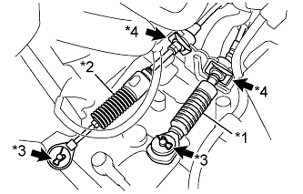 |
Install the control select cable and control shift cable to manual transaxle with the 2 clips A and 2 washers
| 2. CONNECT TRANSMISSION CONTROL CABLE ASSEMBLY |
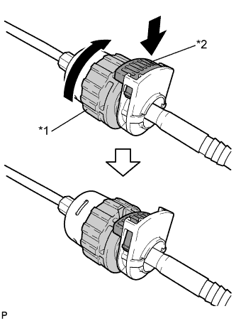
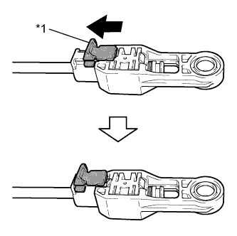
Rotate the transmission control cable nut counterclockwise 180° and push in the lock while holding the nut.
Text in Illustration *1 Nut *2 Lock
 |
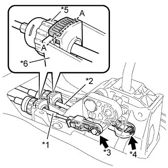
Install the transmission control cable's cable outer onto the shift lever plate.
Text in Illustration *1 Control Select Cable *2 Control Shift Cable *3 Clip A *4 Clip B *5 Nut *6 Shift Lever Plate - NOTICE:
- After installation, check that the cable outer lock extends past the line A-A, as shown in the diagram.
 |
Install the control shift cable to the shift lever assembly with the clip B.
Install the control select cable to the shift lever assembly with the clip A.
- NOTICE:
- Install the cable end adjustment mechanism so that the lock faces the driver seat.
| 3. ADJUST TRANSMISSION CONTROL CABLE ASSEMBLY |
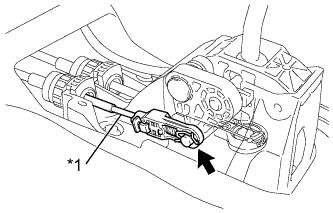
Remove the clip and disconnect the control select cable from the floor shift shift lever assembly.
Text in Illustration *1 Control Select Cable
 |
Slide the adjuster case cover in the direction shown in the illustration.
Text in Illustration *1 Adjuster Case Cover
 |
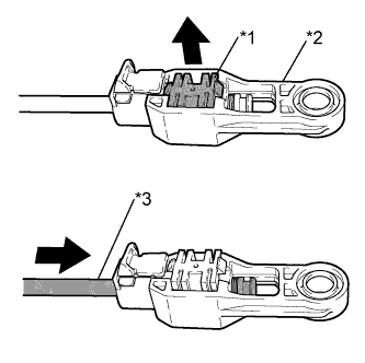
Pull out the lock piece from the adjuster case.
Text in Illustration *1 Lock Piece *2 Adjuster Case *3 Cable Rod
 |
Install the control select cable to the floor shift shift lever assembly with the clip.
- NOTICE:
- Make sure to adjust the length at the neutral shift position.
- Make sure that the lock piece is protruding from the adjuster case.
Gently pull the cable rod toward the rear of the vehicle by hand to pull the cable taut.
Press the lock piece into the adjuster case and lock it.
Slide the adjuster case cover in the direction shown in the illustration.
Text in Illustration *1 Adjuster Case Cover - NOTICE:
- Slide the cover past the protrusion portion of the lock piece.
 |
| 4. INSTALL FRONT NO. 1 FLOOR HEAT INSULATOR |
Install the front No. 1 floor heat insulator with the 2 bolts.
- Torque:
- 5.5 N*m{56 kgf*cm, 49 in.*lbf}
| 5. INSTALL FRONT EXHAUST PIPE ASSEMBLY |
Using a vernier caliper, measure the free length of the compression spring.
- Minimum length:
- 41.5 mm (1.634 in.)
- HINT:
- If the length is not as specified, replace the compression spring.
 |
Hang the front exhaust pipe assembly with the 3 exhaust pipe supports.
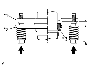
Install the front exhaust pipe assembly onto the exhaust manifold with the 2 compression springs and 2 bolts.
Text in Illustration *1 Exhaust Manifold *2 Front Exhaust Pipe Assembly *3 Exhaust Pipe Gasket *a Space between flanges: 8.5 mm (0.335 in.) - Torque:
- 43 N*m{438 kgf*cm, 32 ft.*lbf}
- HINT:
- After the installation, check that the gaps between the flanges of the exhaust manifold and front exhaust pipe assembly are consistent front-to-rear and left-to-right.
 |
| 6. INSTALL FRONT FLOOR CENTER BRACE (w/ Side Mudguard) |
Install the front floor center brace onto the body with the 2 bolts.
- Torque:
- 30 N*m{307 kgf*cm, 22 ft.*lbf}
| 7. INSTALL AIR CLEANER CAP W/ AIR CLEANER HOSE |
Install the air cleaner case onto the air cleaner bracket with the 2 bolts.
- Torque:
- 7.8 N*m{80 kgf*cm, 69 in.*lbf}
Engage the clamp and connect the wire harness to the air cleaner case.
Install the air cleaner element onto the air cleaner case.
Install the air cleaner cap sub-assembly with No. 1 air cleaner hose onto the throttle body assembly
Engage the 2 clamps and connect the air cleaner cap sub-assembly to the air cleaner case sub-assembly.
Tighten the hose clamp.
- Torque:
- 3.0 N*m{31 kgf*cm, 27 in.*lbf}
Connect the vacuum switching valve assembly connector.
Connect the mass air flow meter connector.
Engage the 2 clamps and connect the wire harness to the air cleaner cap sub-assembly and vacuum switching valve assembly.
Connect the No. 2 fuel vapor feed hose to the intake manifold.
Connect the fuel vapor feed hose assembly to the No. 1 air cleaner hose and vacuum switching valve assembly with the 2 hose clamps.
Engage the clamp and connect the fuel vapor feed hose assembly to the No. 1 air cleaner hose.
| 8. INSTALL REAR CONSOLE BOX ASSEMBLY |
| 9. INSPECT FOR EXHAUST GAS LEAK |