TYPICAL MALFUNCTION THRESHOLDS
CHECK HARNESS AND CONNECTOR (A/F SENSOR - ECM)
CHECK WHETHER DTC OUTPUT RECURS (DTC P2237, P2238, P2239, P2252 OR P2253)
DTC P2237 Oxygen (A/F) Sensor Pumping Current Circuit / Open (Bank 1 Sensor 1) |
DTC P2238 Oxygen (A/F) Sensor Pumping Current Circuit Low (Bank 1 Sensor 1) |
DTC P2239 Oxygen (A/F) Sensor Pumping Current Circuit High (Bank 1 Sensor 1) |
DTC P2252 Oxygen (A/F) Sensor Reference Ground Circuit Low (Bank 1 Sensor 1) |
DTC P2253 Oxygen (A/F) Sensor Reference Ground Circuit High (Bank 1 Sensor 1) |
DESCRIPTION
- HINT:
- Although the DTC titles say oxygen sensor, these DTCs relate to the Air-Fuel Ratio (A/F) sensor.
- Sensor 1 refers to the sensor mounted in front of the Three-Way Catalytic Converter (TWC) and located near the engine assembly.
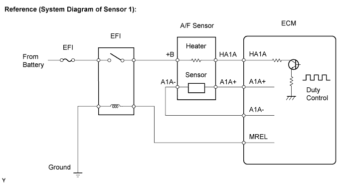
Depending on the engine operating conditions, the heater heats the sensor elements to activate them. Battery voltage is applied to the heater, and the sensor ground is controlled by the ECM using a duty ratio.
The sensor elements convert the oxygen concentration in the exhaust gas into voltage values to output. Based on the voltage, the ECM determines the air-fuel ratio and regulates the fuel injection volume depending on the air-fuel ratio and engine operating conditions. The voltage changes between 0.6 V and 4.5 V while the engine is running. If the air-fuel ratio is lean, which means that the oxygen concentration in the exhaust gas is high, the voltage is high. If the air-fuel ratio is rich, which means that the oxygen concentration in the exhaust gas is low, the voltage is low.

| DTC No. | DTC Detection Condition | Trouble Area |
| P2237 | Open in the circuit between terminals A1A+ and A1A- of the Air-Fuel Ratio (A/F) sensor while engine is running (2 trip detection logic) |
|
| P2238 |
|
|
| P2239 | A1A+ voltage more than 4.5 V (2 trip detection logic) |
|
| P2252 | A1A- voltage 0.5 V or less (2 trip detection logic) |
|
| P2253 | A1A- voltage more than 4.5 V (2 trip detection logic) |
|
MONITOR DESCRIPTION
These DTCs are output when there is an open or short in the Air-Fuel Ratio (A/F) sensor circuit, or if A/F sensor output drops. To detect these problems, the voltage of the A/F sensor is monitored when turning the ignition switch to the ON position, and the admittance (admittance is an electrical term that indicates the ease of flow of current) is checked while driving. If the voltage of the A/F sensor is between 0.6 V and 4.5 V, it is considered normal. If the voltage is out of the specified range, or the admittance is less than the standard value, the ECM will determine that there is a malfunction in the A/F sensor. If the same malfunction is detected in next driving cycle, the MIL will be illuminated and a DTC will be stored.MONITOR STRATEGY
| Related DTCs | P2237: Air-Fuel Ratio (A/F) sensor open circuit between A1A+ and A1A- P2238: A/F sensor short circuit between A1A+ and A1A- P2238: A/F sensor short circuit between A1A+ and GND P2238: A/F sensor low impedance P2239: A/F sensor short circuit between A1A+ and +B P2252: A/F sensor short circuit between A1A- and GND P2253: A/F sensor short circuit between A1A- and +B |
| Required Sensors/Components (Main) | A/F sensor |
| Required Sensors/Components (Related) | Engine Coolant Temperature (ECT) sensor Crankshaft position sensor |
| Frequency of Operation | Continuous |
| Duration | 10 seconds: Air fuel ratio sensor open circuit between AF+ and AF- and low impedance 5 seconds: other |
| MIL Operation | 2 driving cycles |
| Sequence of Operation | None |
TYPICAL ENABLING CONDITIONS
| Monitor runs whenever following DTCs are not present | P0016 (VVT system- misalignment) P0031, P0032 (A/F sensor heater) P0100, P0102, P0103 (MAF meter) P0110, P0112, P0113 (IAT sensor) P0115, P0117, P0118 (ECT sensor) P0120 - P0123, P0220, P0222, P0223, P2135 (TP sensor) P0125 (Insufficient ECT for Closed Loop) P0128 (Thermostat) P0171, P0172 (Fuel system) P0301 - P0304 (Misfire) P0335 (CKP sensor) P0340 (CMP sensor) P0450 - P0453 (EVAP system) P0500 (VSS) P0505 (ISC) P0722 (VSS) |
| Estimated sensor temperature | 450 to 550°C (842 to 1022°F) |
| Engine | Running |
| Battery voltage | 11 V or more |
| Estimated sensor temperature | 700 to 800°C (1292 to 1472°F) |
| Engine coolant temperature | 5°C (41°F) or higher |
| Fuel cut | Not executed |
| Battery voltage | 11 V or more |
| Ignition switch | ON |
| Time after ignition switch is OFF to ON | 5 seconds or more |
TYPICAL MALFUNCTION THRESHOLDS
| A/F sensor admittance | Below 0.002 1/Ω |
| A/F sensor admittance | Below 0.022 1/Ω |
| A1A+ terminal voltage | 0.5 V or less |
| A1A+ terminal voltage | More than 4.5 V |
| A1A- terminal voltage | 0.5 V or less |
| A1A- terminal voltage | More than 4.5 V |
| Difference between A1A+ terminal and A1A- terminal voltage | 0.1 V or less |
COMPONENT OPERATING RANGE
| A/F sensor admittance | 0.022 1/Ω or more |
| A1A+ terminal voltage | 0.6 to 4.5 V |
| A1A- terminal voltage | 0.6 to 4.5 V |
| Difference between A1A+ and A1A- terminal voltages | 0.1 to 0.8 V |
CONFIRMATION DRIVING PATTERN
- Connect the Techstream to the DLC3.
- Turn the ignition switch to ON and turn the Techstream on.
- Clear DTCs (even if no DTCs are stored, perform the clear DTC operation).
- Turn the ignition switch off and wait for at least 30 seconds.
- Turn the ignition switch to ON and turn the Techstream on.
- Start the engine and wait 5 minutes.
- Enter the following menus: Powertrain / Engine and ECT / Trouble Codes.
- Read pending DTCs.
- HINT:
- If a pending DTC is output, the system is malfunctioning.
- If a pending DTC is not output, perform the following procedure.
- Enter the following menus: Powertrain / Engine and ECT / Utility / All Readiness.
- Input the DTC: P2237, P2238, P2239, P2252 or P2253.
- Check the DTC judgment result.
Techstream Display Description NORMAL - DTC judgment completed
- System normal
ABNORMAL - DTC judgment completed
- System abnormal
INCOMPLETE - DTC judgment not completed
- Perform driving pattern after confirming DTC enabling conditions
N/A - Unable to perform DTC judgment
- Number of DTCs which do not fulfill DTC preconditions has reached ECU memory limit
- HINT:
- If the judgment result shows NORMAL, the system is normal.
- If the judgment result shows ABNORMAL, the system has a malfunction.
- If the judgment result shows INCOMPLETE or N/A, idle the engine for 5 minutes and check the DTC judgment result again.
- DTC judgment completed
- If no pending DTC is output, perform a universal trip and check for permanent DTCs (YARIS_NCP93 RM000000PDK0QGX.html).
- HINT:
- If a permanent DTC is output, the system is malfunctioning.
- If no permanent DTC is output, the system is normal.
WIRING DIAGRAM
Refer to DTC P2195 (YARIS_NCP93 RM000000WC40K6X_07.html).INSPECTION PROCEDURE
- NOTICE:
- Inspect the fuses for circuits related to this system before performing the following inspection procedure.
- HINT:
- Read freeze frame data using the Techstream. The ECM records vehicle and driving condition information as freeze frame data the moment a DTC is stored. When troubleshooting, freeze frame data can help determine if the vehicle was moving or stationary, if the engine was warmed up or not, if the air fuel ratio was lean or rich, and other data from the time the malfunction occurred.
- A low air fuel ratio sensor voltage could be caused by a rich air-fuel mixture. Check for conditions that would cause the engine to run rich.
- A high air fuel ratio sensor voltage could be caused by a lean air-fuel mixture. Check for conditions that would cause the engine to run lean.
- Sensor 1 refers to the sensor closest to the engine assembly.
- Sensor 2 refers to the sensor farthest away from the engine assembly.
| 1.CHECK HARNESS AND CONNECTOR (A/F SENSOR - ECM) |
Disconnect the A/F sensor connector.
Disconnect the ECM connector.
Measure the resistance according to the value(s) in the table below.
- Standard Resistance (Check for Open):
Tester Connection Condition Specified Condition HA1A (C23-1) - HA1A (C20-109) Always Below 1 Ω A1A+ (C23-3) - A1A+ (C20-112) Always Below 1 Ω A1A- (C23-4) - A1A- (C20-113) Always Below 1 Ω
- Standard Resistance (Check for Short):
Tester Connection Condition Specified Condition HA1A (C23-1) - HA1A (C20-109) Body ground Always 10 kΩ or higher A1A+ (C23-3) - A1A+ (C20-112) Body ground Always 10 kΩ or higher A1A- (C23-4) - A1A- (C20-113) Body ground Always 10 kΩ or higher
Reconnect the ECM connector.
Reconnect the A/F sensor connector.
|
| ||||
| OK | |
| 2.REPLACE AIR-FUEL RATIO SENSOR |
Replace the A/F sensor (YARIS_NCP93 RM000001CKA00YX.html).
| NEXT | |
| 3.CHECK WHETHER DTC OUTPUT RECURS (DTC P2237, P2238, P2239, P2252 OR P2253) |
Connect the Techstream to the DLC3.
Turn the ignition switch to ON.
Turn the Techstream on.
Clear DTCs (YARIS_NCP93 RM000000PDK0QGX.html).
Turn the ignition switch off and wait for at least 30 seconds.
Turn the ignition switch to ON.
Turn the Techstream on.
Drive the vehicle in accordance with the driving pattern described in the Confirmation Driving Pattern.
Enter the following menus: Powertrain / Engine and ECT / Utility / All Readiness.
Input the DTC: P2237, P2238, P2239, P2252 or P2253.
Check the DTC judgment.
Result Result Proceed to NORMAL (DTC is not output) A ABNORMAL (DTC P2237, P2238, P2239, P2252 or P2253 is output) B
|
| ||||
| A | ||
| ||