Front Axle Hub (For Hatchback) Removal
REMOVE FRONT WHEEL
REMOVE FRONT AXLE SHAFT NUT
SEPARATE FRONT SPEED SENSOR (w/ ABS)
SEPARATE FRONT DISC BRAKE CALIPER ASSEMBLY
REMOVE FRONT DISC
SEPARATE TIE ROD END SUB-ASSEMBLY
SEPARATE FRONT LOWER SUSPENSION ARM
SEPARATE FRONT STABILIZER LINK ASSEMBLY
REMOVE FRONT AXLE ASSEMBLY
REMOVE FRONT AXLE HUB HOLE SNAP RING
REMOVE FRONT AXLE HUB SUB-ASSEMBLY
REMOVE FRONT AXLE HUB BEARING
Front Axle Hub (For Hatchback) -- Removal |
- HINT:
- Use the same procedure for the RH side as for the LH side.
- The procedure listed below is for the LH side.
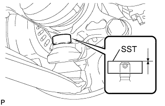
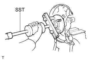
| 2. REMOVE FRONT AXLE SHAFT NUT |
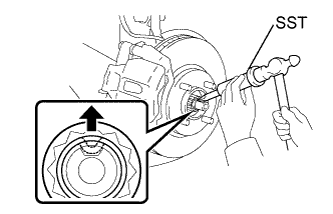
Using SST and a hammer, release the staked part of the front axle shaft nut.
- SST
- 09930-00010
- NOTICE:
- Insert SST into the groove with the flat surface facing up.
- Do not damage the tip of SST using grinders.
- Completely unstake the staked part before removing the front axle shaft nut.
- Do not damage the threads of the front drive shaft.
Using a deep socket wrench 30 mm, remove the front axle shaft nut.
| 3. SEPARATE FRONT SPEED SENSOR (w/ ABS) |
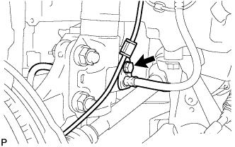
Remove the bolt and separate the speed sensor and flexible hose.
Remove the bolt and separate the speed sensor from the steering knuckle.
- NOTICE:
- Keep the speed sensor tip and installation portion free of foreign matter.
- Remove the speed sensor without turning it from its original installation angle.
| 4. SEPARATE FRONT DISC BRAKE CALIPER ASSEMBLY |
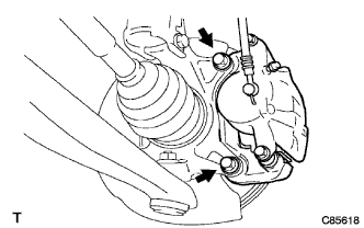
Remove the 2 bolts and separate the disc brake caliper assembly.
- NOTICE:
- Hang the caliper using a piece of string or the equivalent.
Place matchmarks on the disc and axle hub and remove the disc.
Text in Illustration*a
| Matchmark
|
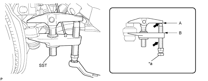
| 6. SEPARATE TIE ROD END SUB-ASSEMBLY |
Remove the cotter pin and castle nut.
Install SST to the threaded section of the tie rod end.
- SST
- 09960-20010(09961-02060)
- NOTICE:
- Make sure the upper ends of the threaded section of the tie rod end and SST are aligned.
Using SST, separate the tie rod end from the front axle assembly.
Text in Illustration*a
| Place the wrench here
| -
| -
|

| Apply grease to the bolt threads and the tip of SST.
| -
| -
|
- SST
- 09960-20010(09961-02010)
- NOTICE:
- Make sure to tie the string of SST to the vehicle to prevent SST from dropping.
- Install SST so that A and B are parallel.
- Be sure to place the wrench on the part indicated in the illustration.
- Do not damage the ball joint dust cover.
- Do not damage the front disc brake dust cover.
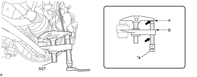
| 7. SEPARATE FRONT LOWER SUSPENSION ARM |
Remove the clip and castle nut.
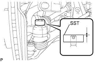
Install SST to the threaded section of the lower ball joint.
- SST
- 09960-20010(09961-02060)
- NOTICE:
- Make sure the upper ends of the threaded section of the lower ball joint and SST are aligned.
Using SST, separate the lower arm.
Text in Illustration*a
| Place the wrench here
| -
| -
|
| Apply grease to the bolt threads and the tip of SST.
| -
| -
|
- SST
- 09960-20010(09961-02010)
- NOTICE:
- Make sure to tie the string of SST to the vehicle to prevent SST from dropping.
- Install SST so that A and B are parallel.
- Be sure to place the wrench on the part indicated in the illustration.
- Do not damage the lower ball joint dust cover.
- Do not damage the drive shaft outboard joint boots.
- Do not damage the front disc brake dust cover.
| 8. SEPARATE FRONT STABILIZER LINK ASSEMBLY |
Remove the nut and separate the front stabilizer link assembly from the shock absorber.
- HINT:
- Using a socket hexagon wrench 6 to hold the stud.
| 9. REMOVE FRONT AXLE ASSEMBLY |
Using a plastic hammer, tap the end of the drive shaft and separate the fitting between the drive shaft and front axle hub.
- NOTICE:
- Do not hammer the threads of the drive shaft.
- HINT:
- If it is difficult to separate the fitting, tap the end of the drive shaft with a brass bar and hammer.
Remove the 2 nuts, 2 bolts and the front axle assembly.
- NOTICE:
- Do not damage the lower ball joint.
- Do not damage the threads of the drive shaft.
- Do not damage the speed sensor rotor.
- Do not damage the drive shaft outboard joint boot.
- Suspend the drive shaft with a piece of string or equivalent.
- HINT:
- Keep the bolt from rotating while turning the nut.
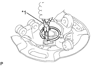
| 10. REMOVE FRONT AXLE HUB HOLE SNAP RING |
Using snap ring pliers, remove the axle hub hole snap ring.
Text in Illustration*1
| Snap Ring Pliers
|
- NOTICE:
- When removing the hole snap ring, do not damage the magnetic rotor surface.
| 11. REMOVE FRONT AXLE HUB SUB-ASSEMBLY |
Fix the steering knuckle in a vise between aluminum plates.
- NOTICE:
- Do not overtighten the vise.
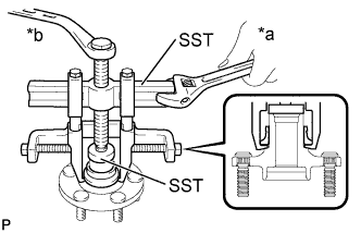
Using SST, remove the axle hub.
- SST
- 09520-00031
Using SST, remove the axle hub bearing inner race.
Text in Illustration*a
| Hold
|
*b
| Turn
|
- SST
- 09950-40011(09951-04020,09952-04010,09953-04020,09954-04010,09955-04011,09957-04010,09958-04011)
09950-60010(09951-00370)
- NOTICE:
- When removing the inner race, it the axle hub is damaged, replace the axle hub with a new one.
- Apply a small amount of grease to the threads and tip of SST before use.
| 12. REMOVE FRONT AXLE HUB BEARING |
(YARIS_NCP93 RM000001IWN01FX.html)