Manual Transaxle Assembly (For Hatchback) Removal
DRAIN TRANSAXLE OIL
REMOVE FRONT WIPER MOTOR AND LINK
REMOVE FRONT NO.1 VENTILATOR SEAL
REMOVE FRONT AIR SHUTTER SEAL RH
REMOVE INNER COWL TOP TO COWL BRACE
REMOVE OUTER COWL TOP PANEL
REMOVE BATTERY
REMOVE BATTERY TRAY
REMOVE BATTERY CARRIER
REMOVE AIR CLEANER ASSEMBLY
REMOVE AIR CLEANER BRACKET
REMOVE STARTER ASSEMBLY (for Cold Area Specification Vehicles)
REMOVE STARTER ASSEMBLY (except Cold Area Specification Vehicles)
SEPARATE CLUTCH RELEASE CYLINDER ASSEMBLY
SEPARATE TRANSMISSION CONTROL CABLE ASSEMBLY
REMOVE CONTROL CABLE BRACKET
DISCONNECT WIRE HARNESS (w/ ABS)
DISCONNECT WIRE HARNESS (w/o ABS)
REMOVE FRONT SUSPENSION CROSSMEMBER SUB-ASSEMBLY
SUPPORT ENGINE AND TRANSAXLE
REMOVE TRANSVERSE ENGINE ENGINE MOUNTING CONTROL BRACKET
SUPPORT MANUAL TRANSAXLE ASSEMBLY
REMOVE TRANSVERSE ENGINE ENGINE MOUNTING INSULATOR
REMOVE TRANSVERSE ENGINE ENGINE MOUNTING BRACKET
REMOVE MANUAL TRANSAXLE ASSEMBLY
REMOVE SPEEDOMETER DRIVEN HOLE COVER SUB-ASSEMBLY (w/ ABS)
REMOVE SPEEDOMETER SENSOR (w/o ABS)
REMOVE WIRE HARNESS CLAMP BRACKET
Manual Transaxle Assembly (For Hatchback) -- Removal |
Remove the manual transmission filler plug and the gasket.
Remove the drain plug sub-assembly and gasket, and then drain the manual transaxle oil.
Install a new gasket and the drain plug sub-assembly.
- Torque:
- 39 N*m{400 kgf*cm, 29 ft.*lbf}
| 2. REMOVE FRONT WIPER MOTOR AND LINK |
(YARIS_NCP93 RM000001OV3023X.html)
| 3. REMOVE FRONT NO.1 VENTILATOR SEAL |
Disengage the clamp and remove the front No. 1 ventilator seal.
| 4. REMOVE FRONT AIR SHUTTER SEAL RH |
- HINT:
- Use the same procedure as for the No. 1 ventilator seal.
| 5. REMOVE INNER COWL TOP TO COWL BRACE |
Remove the 2 bolts and the inner cowl top to cowl brace.
| 6. REMOVE OUTER COWL TOP PANEL |
Disengage the 2 clamps and separate the wire harness.
Remove the 8 bolts and the outer cowl top panel.
Disconnect the cable from the battery terminal.
Loosen the 2 nuts and remove the battery clamp.
Remove the battery.
| 9. REMOVE BATTERY CARRIER |
Disengage the 6 clamps and disconnect the wire harness from the battery carrier.
Remove the 5 bolts and the battery carrier.
| 10. REMOVE AIR CLEANER ASSEMBLY |
Disengage the clamp and disconnect the fuel vapor feed hose assembly from the No. 1 air cleaner hose.
Loosen the 2 hose clamps and disconnect the fuel vapor feed hose assembly from the No. 1 air cleaner hose and vacuum switching valve assembly.
Disconnect the No. 2 fuel vapor feed hose from the intake manifold.
Disengage the 2 clamps and disconnect the wire harness from the air cleaner cap sub-assembly and vacuum switching valve assembly.
Disconnect the mass air flow meter connector.
Disconnect the vacuum switching valve connector.
Loosen the hose clamp and disconnect the No. 1 air cleaner hose from the throttle with motor body assembly.
Disengage the 2 clamps and remove the air cleaner cap sub-assembly with No. 1 air cleaner hose.
Remove the air cleaner element.
Disengage the clamp and disconnect the wire harness from the air cleaner case.
Remove the 2 bolts and the air cleaner case from the air cleaner bracket.
| 11. REMOVE AIR CLEANER BRACKET |
Disengage the clamp and disconnect the wire harness from the air cleaner bracket.
Remove the 2 bolts and the air cleaner bracket.
| 12. REMOVE STARTER ASSEMBLY (for Cold Area Specification Vehicles) |
(YARIS_NCP93 RM0000034TC00YX.html)
| 13. REMOVE STARTER ASSEMBLY (except Cold Area Specification Vehicles) |
(YARIS_NCP93 RM000001E2703AX.html)
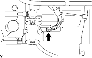
| 14. SEPARATE CLUTCH RELEASE CYLINDER ASSEMBLY |
Remove the 4 bolts, then separate the clutch release cylinder assembly.
- HINT:
- Suspend the clutch release cylinder assembly with a piece of rope so as not to overload the clutch pipe.
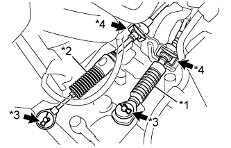
| 15. SEPARATE TRANSMISSION CONTROL CABLE ASSEMBLY |
Remove the clip A and washer, and separate the control shift cable from the manual transaxle assembly.
Text in Illustration*1
| Control Shift Cable
|
*2
| Control Select Cable
|
*3
| Clip A
|
*4
| Clip B
|
Remove the clip B from the control shift cable, and separate the control shift cable from the shift cable bracket.
Remove the clip A and washer, and separate the control select cable from the manual transaxle assembly.
Remove the clip B from the control select cable, and separate the control select cable from the shift cable bracket.
| 16. REMOVE CONTROL CABLE BRACKET |
Remove the 2 bolts and the control cable bracket.
| 17. DISCONNECT WIRE HARNESS (w/ ABS) |
Separate the 4 clamps and remove the bolt, and separate the wire harness from the manual transaxle assembly.
Remove the bolt and separate the ground wire.
Disconnect the back up light switch connector.
| 18. DISCONNECT WIRE HARNESS (w/o ABS) |
Separate the 4 clamps and remove the bolt, and separate the wire harness from the manual transaxle assembly.
Remove the bolt and separate the ground wire.
Disconnect the back up light switch connector.
Disconnect the speedometer sensor connector.
| 19. REMOVE FRONT SUSPENSION CROSSMEMBER SUB-ASSEMBLY |
(YARIS_NCP93 RM000000UNK03LX.html)
| 20. SUPPORT ENGINE AND TRANSAXLE |
On a flat location, set the attachment, plate lift attachment, and wooden block in the positions shown in the figure, and set the engine assembly.
Text in Illustration
| Attachment Placement Positions
|
- NOTICE:
- Set the engine assembly with transaxle so that it is horizontal.
- Never attach the attachment and plate lift attachment to the oil pan section of the manual transaxle.
| 21. REMOVE TRANSVERSE ENGINE ENGINE MOUNTING CONTROL BRACKET |
Remove the 4 bolts and the transverse engine engine mounting control bracket.
| 22. SUPPORT MANUAL TRANSAXLE ASSEMBLY |
Support the manual transaxle assembly with a transmission jack so that it is stable.
| 23. REMOVE TRANSVERSE ENGINE ENGINE MOUNTING INSULATOR |
Remove the bolt and nut, then separate the transverse engine engine mounting insulator from the transverse engine engine mounting bracket.
- HINT:
- Hold the nut and loosen the bolt.
Remove the 5 bolts and the transverse engine engine mounting insulator.
| 24. REMOVE TRANSVERSE ENGINE ENGINE MOUNTING BRACKET |
Remove the 4 bolts and the transverse engine engine mounting bracket from the manual transaxle assembly.
| 25. REMOVE MANUAL TRANSAXLE ASSEMBLY |
Remove the 7 bolts and the manual transaxle assembly.
- NOTICE:
- To prevent damage to the knock pins, do not pry between the transaxle and engine.
- To avoid damage to the input shaft, do not forcefully shake the manual transaxle.
| 26. REMOVE SPEEDOMETER DRIVEN HOLE COVER SUB-ASSEMBLY (w/ ABS) |
Remove the bolt and speedometer driven hole cover sub-assembly from the manual transaxle assembly.
Remove the O-ring from the speedometer driven hole cover sub-assembly.
| 27. REMOVE SPEEDOMETER SENSOR (w/o ABS) |
Remove the bolt and speedometer sensor from the manual transaxle assembly.
Remove the E-ring and speedometer driven gear from the speedometer sensor.
Text in Illustration*1
| Speedometer Driven Gear
|
*2
| O-ring
|
*3
| E-ring
|
Remove the O-ring from the speedometer sensor.
| 28. REMOVE WIRE HARNESS CLAMP BRACKET |
Remove the 3 bolts and 3 wire harness clamp brackets from the manual transaxle assembly.