Dtc B1650/32 Occupant Classification System Malfunction
DESCRIPTION
WIRING DIAGRAM
INSPECTION PROCEDURE
CHECK DTC (OCCUPANT DETECTION ECU)
CHECK CONNECTORS
CHECK OCCUPANT CLASSIFICATION SYSTEM CIRCUIT (OPEN)
CHECK OCCUPANT CLASSIFICATION SYSTEM CIRCUIT (SHORT)
CHECK OCCUPANT CLASSIFICATION SYSTEM CIRCUIT (SHORT TO B+)
CHECK OCCUPANT CLASSIFICATION SYSTEM CIRCUIT (SHORT TO GROUND)
CHECK FLOOR WIRE (OPEN)
CHECK FLOOR WIRE (SHORT)
CHECK FLOOR WIRE (SHORT TO B+)
CHECK FLOOR WIRE (SHORT TO GROUND)
DTC B1650/32 Occupant Classification System Malfunction |
DESCRIPTION
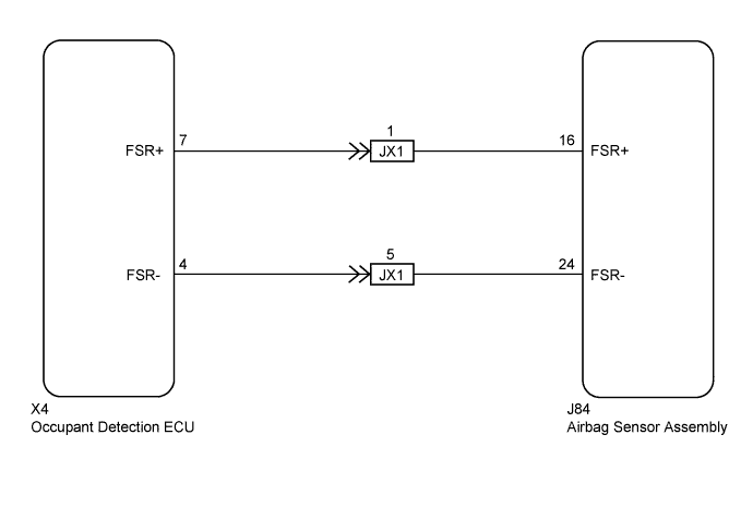
The occupant classification system circuit consists of the airbag sensor assembly and occupant classification system.If the airbag sensor assembly receives signals from the occupant detection ECU, it determines whether the front passenger airbag, front seat side airbag assembly RH and front seat belt pretensioner RH should be operated.DTC B1650/32 is stored when a malfunction is detected in the occupant classification system circuit.DTC No.
| DTC Detection Condition
| Trouble Area
|
B1650/32
| - The airbag sensor assembly receives a line short circuit signal, an open circuit signal, a short circuit to ground signal or a short circuit to B+ signal in the occupant classification system circuit.
- Occupant classification system malfunction
- Airbag sensor assembly malfunction
| - Floor wire
- Front seat wire RH
- Occupant classification system
- Airbag sensor assembly
|
WIRING DIAGRAM
INSPECTION PROCEDURE
| 1.CHECK DTC (OCCUPANT DETECTION ECU) |
Turn the ignition switch to ON.
Check for DTCs of the occupant detection ECU (YARIS_NCP93 RM0000010VK072X.html).
- OK:
- DTC is not output.
Turn the ignition switch off.
Disconnect the cable from the negative (-) battery terminal.
- CAUTION:
- Wait at least 90 seconds after disconnecting the cable from the negative (-) battery terminal to disable the SRS system.
Check that the connectors are properly connected to the airbag sensor assembly and occupant detection ECU. Also check that the connectors that link the floor wire and front seat wire RH are properly connected.
- OK:
- The connectors are properly connected.
- HINT:
- If the connectors are not connected securely, reconnect the connectors and proceed to the next inspection.
Disconnect the connectors from the airbag sensor assembly and occupant detection ECU. Also disconnect the connectors that link the floor wire and front seat wire RH.
Check that the terminals of the connectors are not damaged.
- OK:
- The terminals are not deformed or damaged.
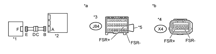
| 3.CHECK OCCUPANT CLASSIFICATION SYSTEM CIRCUIT (OPEN) |
Connect the connectors that link the floor wire and front seat wire RH.
Text in Illustration*1
| Occupant Detection ECU
| *2
| Airbag Sensor Assembly
|
*3
| Connector B
| *4
| Connector E
|
*5
| Service Wire
| -
| -
|
*a
| Front view of wire harness connector
(to Airbag Sensor Assembly)
| *b
| Front view of wire harness connector
(to Occupant Detection ECU)
|
Using the service wire, connect terminals 16 (FSR+) and 24 (FSR-) of connector B.
- NOTICE:
- Do not forcibly insert the service wire into the terminals of the connector when connecting.
Measure the resistance according to the value(s) in the table below.
- Standard Resistance:
Tester Connection
| Condition
| Specified Condition
|
X4-7 (FSR+) - X4-4 (FSR-)
| Always
| Below 1 Ω
|
| 4.CHECK OCCUPANT CLASSIFICATION SYSTEM CIRCUIT (SHORT) |
Disconnect the service wire from connector B.
Measure the resistance according to the value(s) in the table below.
- Standard Resistance:
Tester Connection
| Condition
| Specified Condition
|
X4-7 (FSR+) - X4-4 (FSR-)
| Always
| 1 MΩ or higher
|
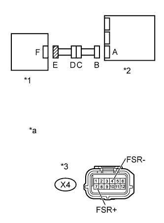
Text in Illustration*1
| Occupant Detection ECU
|
*2
| Airbag Sensor Assembly
|
*3
| Connector E
|
*a
| Front view of wire harness connector
(to Occupant Detection ECU)
|
| 5.CHECK OCCUPANT CLASSIFICATION SYSTEM CIRCUIT (SHORT TO B+) |
Connect the cable to the negative (-) battery terminal.
Turn the ignition switch to ON.
Measure the voltage according to the value(s) in the table below.
- Standard Voltage:
Tester Connection
| Switch Condition
| Specified Condition
|
X4-7 (FSR+) - Body ground
| Ignition switch ON
| Below 1 V
|
X4-4 (FSR-) - Body ground
| Ignition switch ON
| Below 1 V
|
Text in Illustration*1
| Occupant Detection ECU
|
*2
| Airbag Sensor Assembly
|
*3
| Connector E
|
*a
| Front view of wire harness connector
(to Occupant Detection ECU)
|
| 6.CHECK OCCUPANT CLASSIFICATION SYSTEM CIRCUIT (SHORT TO GROUND) |
Turn the ignition switch off.
Disconnect the cable from the negative (-) battery terminal.
- CAUTION:
- Wait at least 90 seconds after disconnecting the cable from the negative (-) battery terminal to disable the SRS system.
Measure the resistance according to the value(s) in the table below.
- Standard Resistance:
Tester Connection
| Condition
| Specified Condition
|
X4-7 (FSR+) - Body ground
| Always
| 1 MΩ or higher
|
X4-4 (FSR-) - Body ground
| Always
| 1 MΩ or higher
|
Text in Illustration*1
| Occupant Detection ECU
|
*2
| Airbag Sensor Assembly
|
*3
| Connector E
|
*a
| Front view of wire harness connector
(to Occupant Detection ECU)
|
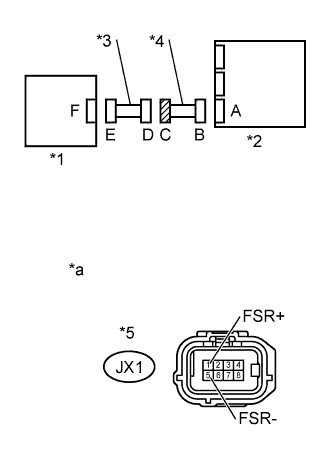
| 7.CHECK FLOOR WIRE (OPEN) |
Disconnect the front seat wire RH from the floor wire.
Text in Illustration*1
| Occupant Detection ECU
| *2
| Airbag Sensor Assembly
|
*3
| Front Seat Wire RH
| *4
| Floor Wire
|
*5
| Connector B
| *6
| Connector C
|
*7
| Service Wire
| -
| -
|
*a
| Front view of wire harness connector
(to Airbag Sensor Assembly)
| *b
| Front view of wire harness connector
(to Front Seat Wire RH)
|
- HINT:
- The service wire has already been inserted into connector B.
Measure the resistance according to the value(s) in the table below.
- Standard Resistance:
Tester Connection
| Condition
| Specified Condition
|
JX1-1 (FSR+) - JX1-5 (FSR-)
| Always
| Below 1 Ω
|
Disconnect the service wire from the connector B.
| OK |
|
|
|
| REPLACE FRONT SEAT WIRE RH |
|
| 8.CHECK FLOOR WIRE (SHORT) |
Disconnect the front seat wire RH from the floor wire.
Measure the resistance according to the value(s) in the table below.
- Standard Resistance:
Tester Connection
| Condition
| Specified Condition
|
JX1-1 (FSR+) - JX1-5 (FSR-)
| Always
| 1 MΩ or higher
|
Text in Illustration*1
| Occupant Detection ECU
|
*2
| Airbag Sensor Assembly
|
*3
| Front Seat Wire RH
|
*4
| Floor Wire
|
*5
| Connector C
|
*a
| Front view of wire harness connector
(to Front Seat Wire RH)
|
| OK |
|
|
|
| REPLACE FRONT SEAT WIRE RH |
|
| 9.CHECK FLOOR WIRE (SHORT TO B+) |
Turn the ignition switch off.
Disconnect the cable from the negative (-) battery terminal.
- CAUTION:
- Wait at least 90 seconds after disconnecting the cable from the negative (-) battery terminal to disable the SRS system.
Disconnect the front seat wire RH from the floor wire.
Connect the cable to the negative (-) battery terminal.
Turn the ignition switch to ON.
Measure the voltage according to the value(s) in the table below.
- Standard Voltage:
Tester Connection
| Switch Condition
| Specified Condition
|
JX1-1 (FSR+) - Body ground
| Ignition switch ON
| Below 1 V
|
JX1-5 (FSR-) - Body ground
| Ignition switch ON
| Below 1 V
|
Text in Illustration*1
| Occupant Detection ECU
|
*2
| Airbag Sensor Assembly
|
*3
| Front Seat Wire RH
|
*4
| Floor Wire
|
*5
| Connector C
|
*a
| Front view of wire harness connector
(to Front Seat Wire RH)
|
| OK |
|
|
|
| REPLACE FRONT SEAT WIRE RH |
|
| 10.CHECK FLOOR WIRE (SHORT TO GROUND) |
Disconnect the front seat wire RH from the floor wire.
Measure the resistance according to the value(s) in the table below.
- Standard Resistance:
Tester Connection
| Condition
| Specified Condition
|
JX1-1 (FSR+) - Body ground
| Always
| 1 MΩ or higher
|
JX1-5 (FSR-) - Body ground
| Always
| 1 MΩ or higher
|
Text in Illustration*1
| Occupant Detection ECU
|
*2
| Airbag Sensor Assembly
|
*3
| Front Seat Wire RH
|
*4
| Floor Wire
|
*5
| Connector C
|
*a
| Front view of wire harness connector
(to Front Seat Wire RH)
|
| OK |
|
|
|
| REPLACE FRONT SEAT WIRE RH |
|