Dtc P0571 Stop Light Switch Circuit Malfunction
DESCRIPTION
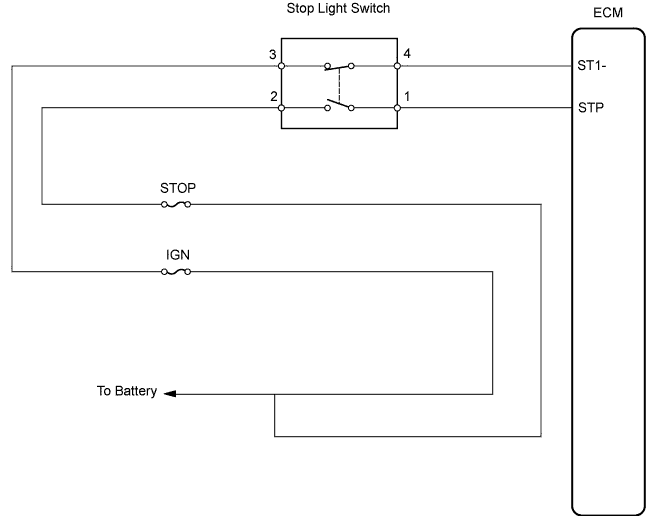
WIRING DIAGRAM
INSPECTION PROCEDURE
INSPECT STOP LIGHT SWITCH OPERATION
INSPECT STOP LIGHT SWITCH ASSEMBLY
INSPECT ECM (STP SIGNAL)
DTC P0571 Stop Light Switch Circuit Malfunction |
DESCRIPTION
The cruise control system cancels cruising when the ECM detects that the brake pedal is depressed during cruise control driving. The stop light switch assembly sends signals to the ECM according to the brake pedal conditions. When the brake pedal is released, terminal ST1- is the positive (+) battery voltage, and terminal STP voltage is below 1 V. While the brake pedal is depressed, terminal ST1- is below 1 V, and STP is positive (+) battery voltage. During braking, the ECM cancels cruise control as one of the manual cancel functions.The ECM outputs this trouble code when the voltage of terminals ST1- and STP are both below 1 V for 0.5 seconds or more at the same time.The fail-safe function operates to enable normal driving even if there is a malfunction in the stop light signal circuit.DTC No.
| DTC Detected Conditions
| Trouble Areas
|
P0571
| ECM detects a malfunction of the stop light switch circuit under both of the following conditions.
- Voltage of terminal STP is below 1 V for 0.5 seconds or more.
- Voltage of terminal ST1- is below 1 V for 0.5 seconds or more.
| - Stop light switch assembly
- Stop light switch assembly circuit
- ECM
|
WIRING DIAGRAM
INSPECTION PROCEDURE
| 1.INSPECT STOP LIGHT SWITCH OPERATION |
Check that the stop lights come on while the brake pedal is depressed, and go off when the brake pedal is released.
- OK:
Brake Pedal Condition
| Stop Light Condition
|
Depressed
| ON
|
Released
| OFF
|
| | INSPECT STOP LIGHT SWITCH CIRCUIT |
|
|
| 2.INSPECT STOP LIGHT SWITCH ASSEMBLY |
Disconnect the stop light switch assembly connector.
Measure the resistance.
- Standard resistance:
Tester Connection
| Switch Condition
| Stop Light Condition
|
1 - 2
| Switch pin free
(Brake pedal depressed)
| Below 1Ω
|
3 - 4
| Switch pin free
(Brake pedal depressed)
| 10 kΩ or higher
|
1 - 2
| Switch pin pushed in
(Brake pedal released)
| 10 kΩ or higher
|
3 - 4
| Switch pin pushed in
(Brake pedal released)
| Below 1Ω
|
Reconnect the stop light switch assembly connector.
| 3.INSPECT ECM (STP SIGNAL) |
Disconnect the A21 ECM connector.
Turn the ignition switch to the ON position.
Measure the voltage.
- Standard voltage:
Tester Connection
| Brake Pedal Condition
| Specified Condition
|
STP (A21-36) - Body ground
| Depressed
| 10 to 14 V
|
STP (A21-36) - Body ground
| Released
| Below 1V
|
ST1- (A21-35) - Body ground
| Depressed
| Below 1V
|
ST1- (A21-35) - Body ground
| Released
| 10 to 14 V
|
Reconnect the ECM connector.
| | REPAIR OR REPLACE HARNESS OR CONNECTOR (STOP LIGHT SWITCH ASSEMBLY - ECM) |
|
|