Dtc P0340 Camshaft Position Sensor A Circuit (Bank 1 Or Single Sensor)
DESCRIPTION
MONITOR DESCRIPTION
MONITOR STRATEGY
TYPICAL ENABLING CONDITIONS
TYPICAL MALFUNCTION THRESHOLDS
COMPONENT OPERATING RANGE
CONFIRMATION DRIVING PATTERN
WIRING DIAGRAM
INSPECTION PROCEDURE
INSPECT CAMSHAFT POSITION SENSOR
CHECK HARNESS AND CONNECTOR (CAMSHAFT POSITION SENSOR - ECM)
CHECK SENSOR INSTALLATION (CAMSHAFT POSITION SENSOR)
CHECK VALVE TIMING
CHECK CAMSHAFT (TIMING ROTOR)
REPLACE CAMSHAFT POSITION SENSOR
CHECK WHETHER DTC OUTPUT RECURS (DTC P0340)
DTC P0340 Camshaft Position Sensor "A" Circuit (Bank 1 or Single Sensor) |
DESCRIPTION
The Camshaft Position (CMP) sensor consists of a magnet and an iron core which is wrapped with copper wire, and is installed onto the cylinder head. When the camshaft rotates, each of 3 teeth on the camshaft passes through the CMP sensor. This activates the internal magnet in the sensor, generating a voltage in the copper wire. The camshaft rotation is synchronized with the crankshaft rotation. When the crankshaft turns twice, the voltage is generated 3 times in the CMP sensor. The generated voltage in the sensor acts as a signal, allowing the ECM to locate the camshaft position. This signal is then used to control ignition timing, fuel injection timing, and the VVT system.DTC No.
| DTC Detection Condition
| Trouble Area
|
P0340
| Case 1
- No Camshaft Position (CMP) sensor signal to ECM while cranking (2 trip detection logic)
Case 2
- Camshaft/Crankshaft misalignment detected at engine speed of 600 rpm or more (1 trip detection logic)
| - Open or short in CMP sensor circuit
- CMP sensor
- Camshaft
- Jumped tooth of timing chain
- ECM
|
- HINT:
- DTC P0340 indicates a malfunction relating to the CMP sensor (+) circuit (the wire harness between the ECM and CMP sensor, and the CMP sensor itself).
Reference: Inspection using an oscilloscope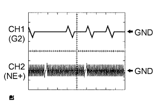
- HINT:
- The correct waveform is as shown in the illustration.
- G2 stands for the CMP sensor signal, and NE+ stands for the Crankshaft Position (CKP) sensor signal.
- Grounding failure of the shielded wire may cause noise in waveforms.
Item
| Content
|
Terminals
| CH1: G2 - NE-
CH2: NE+ - NE-
|
Equipment Settings
| 5 V/DIV, 20 ms/DIV
|
Conditions
| Cranking or idling
|
MONITOR DESCRIPTION
If no signal is transmitted by the CMP sensor despite the engine revolving, or the rotation of the camshaft and the crankshaft is not synchronized, the ECM interprets this as a malfunction of the sensor.If the malfunction is not repaired successfully, a DTC is stored 10 seconds after the engine is next started.
MONITOR STRATEGY
Related DTCs
| P0340: Camshaft position sensor range check
P0340: Camshaft position/crankshaft position misalignment
|
Required Sensors/Components (Main)
| Camshaft Position (CMP) sensor
|
Required Sensors/Components (Related)
| Crankshaft Position (CKP) sensor
|
Frequency of Operation
| Continuous
|
Duration
| 4 seconds: CMP sensor range check
5 seconds: Camshaft position/crankshaft position misalignment
|
MIL Operation
| 2 driving cycles: CMP sensor range check
Immediate: Camshaft position/crankshaft position misalignment
|
Sequence of Operation
| None
|
TYPICAL ENABLING CONDITIONS
All:Monitor runs whenever following DTCs not present
| None
|
Camshaft Position Sensor Verify Pulse Input Case1:Starter
| ON
|
Minimal battery voltage while starter ON
| Less than 11 V
|
Camshaft Position Sensor Verify Pulse Input Case2:Engine speed
| 600 rpm or more
|
Starter
| OFF
|
VVT system misalignment
| Not detected
|
TYPICAL MALFUNCTION THRESHOLDS
Camshaft Position Sensor Range Check:CMP sensor signal
| No signal
|
Camshaft Position/Crankshaft Position Misalignment:Camshaft position and crankshaft position phase
| Misaligned
|
COMPONENT OPERATING RANGE
CMP sensor
| - CMP sensor output voltage fluctuates while camshaft revolving
- 3 CMP sensor signals per 2 crankshaft revolutions
|
CONFIRMATION DRIVING PATTERN
- Connect the Techstream to the DLC3.
- Turn the ignition switch to ON and turn the Techstream on.
- Clear DTCs (even if no DTCs are stored, perform the clear DTC operation).
- Turn the ignition switch off and wait for at least 30 seconds.
- Turn the ignition switch to ON and turn the Techstream on.
- Start the engine.
- Idle the engine for 10 seconds or more [A].
- Enter the following menus: Powertrain / Engine and ECT / Trouble Codes [B].
- Read pending DTCs.
- HINT:
- If a pending DTC is output, the system is malfunctioning.
- If a pending DTC is not output, perform the following procedure.
- Enter the following menus: Powertrain / Engine and ECT / Utility / All Readiness.
- Input the DTC: P0340.
- Check the DTC judgment result.
Techstream Display
| Description
|
NORMAL
| - DTC judgment completed
- System normal
|
ABNORMAL
| - DTC judgment completed
- System abnormal
|
INCOMPLETE
| - DTC judgment not completed
- Perform driving pattern after confirming DTC enabling conditions
|
N/A
| - Unable to perform DTC judgment
- Number of DTCs which do not fulfill DTC preconditions has reached ECU memory limit
|
- HINT:
- If the judgment result shows NORMAL, the system is normal.
- If the judgment result shows ABNORMAL, the system has a malfunction.
- If the judgment result shows INCOMPLETE or N/A, perform steps [A] through [B] again.
- If no pending DTC is output, perform a universal trip and check for permanent DTCs (YARIS_NCP93 RM000000PDK0QGX.html).
- HINT:
- If a permanent DTC is output, the system is malfunctioning.
- If no permanent DTC is output, the system is normal.
WIRING DIAGRAM
Refer to DTC P0335 (YARIS_NCP93 RM000000TCW0MCX_07.html).
INSPECTION PROCEDURE
- HINT:
- Read freeze frame data using the Techstream. The ECM records vehicle and driving condition information as freeze frame data the moment a DTC is stored. When troubleshooting, freeze frame data can help determine if the vehicle was moving or stationary, if the engine was warmed up or not, if the air fuel ratio was lean or rich, and other data from the time the malfunction occurred.
- If no problem is found through this diagnostic troubleshooting procedure, there may be a mechanical problem with the engine.
| 1.INSPECT CAMSHAFT POSITION SENSOR |
Inspect the camshaft position sensor (YARIS_NCP93 RM000001DBJ016X.html).
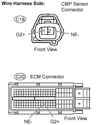
| 2.CHECK HARNESS AND CONNECTOR (CAMSHAFT POSITION SENSOR - ECM) |
Disconnect the C18 CMP sensor connector.
Disconnect the C20 ECM connector.
Check the resistance.
- Standard resistance (Check for open):
Tester Connections
| Specified Conditions
|
G2+ (C18-1) - G2+ (C20-99)
| Below 1 Ω
|
NE- (C18-2) - NE- (C20-121)
|
- Standard resistance (Check for short):
Tester Connections
| Specified Conditions
|
G2+ (C18-1) or G2+ (C20-99) - Body ground
| 10 kΩ or higher
|
NE- (C18-2) or NE- (C20-121) - Body ground
|
Reconnect the ECM connector.
Reconnect the CMP sensor connector.
| | REPAIR OR REPLACE HARNESS OR CONNECTOR |
|
|
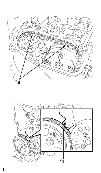
| 3.CHECK SENSOR INSTALLATION (CAMSHAFT POSITION SENSOR) |
Check the CMP sensor installation.
- OK:
- Sensor is installed correctly.
Remove the cylinder head cover.
Turn the crankshaft pulley, and align its groove with the timing mark "0" on the timing chain cover.
Check that the timing marks on the camshaft timing sprocket and camshaft timing gear are facing upward as shown in the illustration.
- If not, turn the crankshaft 1 revolution (360°), then align the marks as above.
- OK:
- Timing marks on camshaft timing gears are aligned as shown in the illustration.
Text in Illustration*a
| Timing Mark
|
Reinstall the cylinder head cover.
| 5.CHECK CAMSHAFT (TIMING ROTOR) |
Check the timing rotor of the camshaft.
- OK:
- Camshaft timing rotor does not have any cracks or deformation.
| 6.REPLACE CAMSHAFT POSITION SENSOR |
Replace the camshaft position sensor (YARIS_NCP93 RM000001DBL011X.html).
| 7.CHECK WHETHER DTC OUTPUT RECURS (DTC P0340) |
Connect the Techstream to the DLC3.
Turn the ignition switch to ON.
Turn the Techstream on.
Clear DTCs (YARIS_NCP93 RM000000PDK0QGX.html).
Drive the vehicle in accordance with the driving pattern described in the Confirmation Driving Pattern.
Read DTCs.
ResultDisplay (DTC Output)
| Proceed To
|
No output
| A
|
P0340
| B
|
- HINT:
- If the engine does not start, replace the ECM.