REPLACE FRONT SEAT INNER BELT ASSEMBLY RH (PASSENGER SIDE BUCKLE SWITCH)
REPLACE OCCUPANT CLASSIFICATION ECU
PERFORM ZERO POINT CALIBRATION AND SENSITIVITY CHECK
DTC B1771 Passenger Side Buckle Switch Circuit Malfunction |
DESCRIPTION
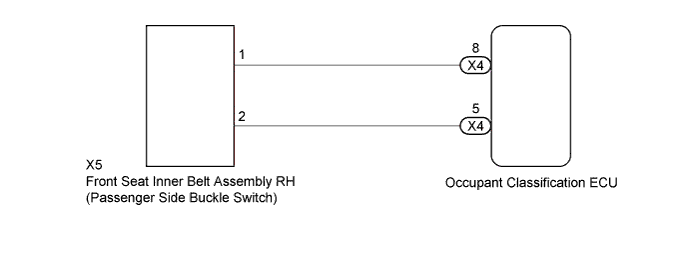
The passenger side buckle switch circuit consists of the occupant classification ECU and the front seat inner belt assembly RH.DTC B1771 is stored when a malfunction is detected in the passenger side buckle switch circuit.
| DTC Code | DTC Detection Condition | Trouble Area |
| B1771 | One of following conditions is met:
|
|
- HINT:
- When DTC B1650/32 is detected as a result of troubleshooting the airbag system, perform troubleshooting for DTC B1771 of the occupant classification system.
- Use the Techstream to check for DTCs of the occupant classification ECU, otherwise the DTC cannot be read.
WIRING DIAGRAM
INSPECTION PROCEDURE
- HINT:
- If troubleshooting (wire harness inspection) is difficult to perform, remove the front seat assembly RH installation bolts to see the undersurface of the seat cushion.
- In the above case, hold the seat so that it does not fall down. Holding the seat for a long period of time may cause a problem, such as seat rail deformation. Hold the seat up only for as long as necessary.
| 1.CHECK FOR DTC |
Turn the ignition switch to ON, and wait for at least 60 seconds.
Clear the DTCs stored in the memory (YARIS_NCP93 RM0000010VK072X.html).
- HINT:
- First clear DTCs stored in the occupant classification ECU and then in the airbag sensor assembly.
- Use the Techstream to clear the DTCs of the occupant classification ECU, otherwise the DTCs cannot be cleared.
Turn the ignition switch off.
Turn the ignition switch to ON, and wait for at least 60 seconds.
Check for DTCs (YARIS_NCP93 RM0000010VK072X.html).
- OK:
- DTC B1771 is not output.
- HINT:
- Codes other than DTC B1771 may be output at this time, but they are not related to this check.
|
| ||||
| OK | ||
| ||
| 2.CHECK CONNECTION OF CONNECTOR |
Turn the ignition switch off.
Disconnect the cable from the negative (-) battery terminal, and wait for at least 90 seconds.
Check that the connectors are properly connected to the occupant classification ECU and the front seat inner belt assembly RH.
- OK:
- Connectors are properly connected.
|
| ||||
| OK | |
| 3.CHECK CONNECTOR |
Disconnect the connectors from the occupant classification ECU and the front seat inner belt assembly RH.
Check that the connectors (on the occupant classification ECU side and front seat inner belt assembly RH side) are not damaged.
- OK:
- Connectors are not deformed or damaged.
|
| ||||
| OK | |
| 4.CHECK FRONT SEAT WIRE RH |
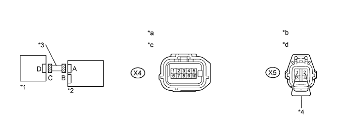
| *1 | Front Seat Inner Belt Assembly RH | *2 | Occupant Classification ECU |
| *3 | Front Seat Wire RH | *4 | Service Wire |
| *a | Front view of wire harness connector (to Occupant Classification ECU) | *b | Front view of wire harness connector (to Front Seat Inner Belt Assembly RH) |
| *c | Connector B | *d | Connector C |
Connect the cable to the negative (-) battery terminal, and wait for at least 2 seconds.
Turn the ignition switch to ON.
Measure the voltage according to the value(s) in the table below.
- Standard Voltage:
Tester Connection Switch Condition Specified Condition X4-5 - Body ground Ignition switch ON Below 1 V X4-8 - Body ground
Turn the ignition switch off.
Disconnect the cable from the negative (-) battery terminal, and wait for at least 90 seconds.
Using a service wire, connect terminals 1 (RBE+) and 2 (RBE-) of connector C.
- NOTICE:
- Do not forcibly insert the service wire into the terminals of the connector.
Measure the resistance according to the value(s) in the table below.
- Standard Resistance:
Tester Connection Condition Specified Condition X4-8 - X4-5 Always Below 1 Ω
Disconnect the service wire from connector C.
Measure the resistance according to the value(s) in the table below.
- Standard Resistance:
Tester Connection Condition Specified Condition X4-5 - Body ground Always 1 MΩ or higher X4-8 - Body ground X4-8 - X4-5
|
| ||||
| OK | |
| 5.CHECK FOR DTC |
Connect the connectors to the occupant classification ECU and the front seat inner belt assembly RH.
Connect the cable to the negative (-) battery terminal, and wait for at least 2 seconds.
Turn the ignition switch to ON, and wait for at least 60 seconds.
Clear the DTCs stored in the memory (YARIS_NCP93 RM0000010VK072X.html).
- HINT:
- First clear DTCs stored in the occupant classification ECU and then in the airbag sensor assembly.
- Use the Techstream to clear the DTCs of the occupant classification ECU, otherwise the DTCs cannot be cleared.
Turn the ignition switch off.
Turn the ignition switch to ON, and wait for at least 60 seconds.
Using the Techstream, check for DTCs of the occupant classification ECU (YARIS_NCP93 RM0000010VK072X.html).
- OK:
- DTC B1771 is not output.
- HINT:
- DTCs other than DTC B1771 may be output at this time, but they are not related to this check.
|
| ||||
| OK | ||
| ||
| 6.REPLACE FRONT SEAT INNER BELT ASSEMBLY RH (PASSENGER SIDE BUCKLE SWITCH) |
Turn the ignition switch off.
Disconnect the cable from the negative (-) battery terminal, and wait for at least 90 seconds.
Replace the front seat inner belt assembly RH (YARIS_NCP93 RM000000SY000TX.html).
- HINT:
- Perform the inspection using parts from a normal vehicle when possible.
Connect the cable to the negative (-) battery terminal, and wait for at least 2 seconds.
| NEXT | |
| 7.CHECK FOR DTC |
Turn the ignition switch to ON, and wait for at least 60 seconds.
Clear the DTCs stored in the memory (YARIS_NCP93 RM0000010VK072X.html).
- HINT:
- First clear DTCs stored in the occupant classification ECU and then in the airbag sensor assembly.
- Use the Techstream to clear the DTCs of the occupant classification ECU, otherwise the DTCs cannot be cleared.
Turn the ignition switch off.
Turn the ignition switch to ON, and wait for at least 60 seconds.
Using the Techstream, check for DTCs of the occupant classification ECU (YARIS_NCP93 RM0000010VK072X.html).
- OK:
- DTC B1771 is not output.
- HINT:
- DTCs other than DTC B1771 may be output at this time, but they are not related to this check.
|
| ||||
| OK | ||
| ||
| 8.REPLACE OCCUPANT CLASSIFICATION ECU |
Turn the ignition switch off.
Disconnect the cable from the negative (-) battery terminal, and wait for at least 90 seconds.
Replace the occupant classification ECU (YARIS_NCP93 RM0000011JG02SX.html).
- HINT:
- Perform the inspection using parts from a normal vehicle when possible.
Connect the cable to the negative (-) battery terminal, and wait for at least 2 seconds.
| NEXT | |
| 9.PERFORM ZERO POINT CALIBRATION AND SENSITIVITY CHECK |
Connect the Techstream to the DLC3.
Turn the ignition switch to ON.
Using the Techstream, perform Zero Point Calibration and Sensitivity Check (YARIS_NCP93 RM0000010VN073X.html).
| NEXT | ||
| ||