Sfi System (For Sedan) Fuel Injector Circuit
DESCRIPTION
WIRING DIAGRAM
INSPECTION PROCEDURE
INSPECT FUEL INJECTOR ASSEMBLY (POWER SOURCE)
INSPECT FUEL INJECTOR ASSEMBLY (INJECTOR RESISTANCE)
CHECK HARNESS AND CONNECTOR (FUEL INJECTOR ASSEMBLY - ECM)
CHECK HARNESS AND CONNECTOR (ECM - BODY GROUND)
INSPECT FUEL INJECTOR ASSEMBLY (INJECTION AND VOLUME)
CHECK HARNESS AND CONNECTOR (FUEL INJECTOR ASSEMBLY - INTEGRATION RELAY)
SFI SYSTEM (for Sedan) - Fuel Injector Circuit |
DESCRIPTION
The fuel injector assembly inject fuel based on the signals from the ECM.
WIRING DIAGRAM
INSPECTION PROCEDURE
- NOTICE:
- Inspect the fuses for circuits related to this system before performing the following inspection procedure.
| 1.INSPECT FUEL INJECTOR ASSEMBLY (POWER SOURCE) |
Disconnect the fuel injector assembly connectors.
Turn the ignition switch to ON.
Measure the voltage according to the value(s) in the table below.
- Standard voltage:
Tester Connections
| Specified Conditions
|
C4-1 - Body ground
| 11 to 14 V
|
C5-1 - Body ground
| 11 to 14 V
|
C6-1 - Body ground
| 11 to 14 V
|
C7-1 - Body ground
| 11 to 14 V
|
Reconnect the fuel injector assembly connectors.
| 2.INSPECT FUEL INJECTOR ASSEMBLY (INJECTOR RESISTANCE) |
Disconnect the fuel injector assembly connectors.
Measure the resistance according to the value(s) in the table below.
- Standard resistance:
Tester Connections
| Specified Conditions
|
1 - 2
| 11.6 to 12.4 Ω at 20°C (68°F)
|
Reconnect the fuel injector assembly connectors.
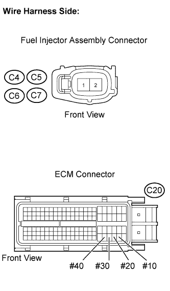
| 3.CHECK HARNESS AND CONNECTOR (FUEL INJECTOR ASSEMBLY - ECM) |
Disconnect the C20 ECM connector.
Disconnect the fuel injector assembly connectors.
Measure the resistance according to the value(s) in the table below.
- Standard resistance (Check for open):
Tester Connections
| Specified Conditions
|
C4-2 - C20-108 (#10)
| Below 1 Ω
|
C5-2 - C20-107 (#20)
| Below 1 Ω
|
C6-2 - C20-106 (#30)
| Below 1 Ω
|
C7-2 - C20-105 (#40)
| Below 1 Ω
|
- Standard resistance (Check for short):
Tester Connections
| Specified Conditions
|
C4-2 or C20-108 (#10) - Body ground
| 10 kΩ or higher
|
C5-2 or C20-107 (#20) - Body ground
| 10 kΩ or higher
|
C6-2 or C20-106 (#30) - Body ground
| 10 kΩ or higher
|
C7-2 or C20-105 (#40) - Body ground
| 10 kΩ or higher
|
Reconnect the fuel injector assembly connectors.
Reconnect the ECM connector.
| | REPAIR OR REPLACE HARNESS OR CONNECTOR |
|
|
| 4.CHECK HARNESS AND CONNECTOR (ECM - BODY GROUND) |
Disconnect the C20 ECM connector.
Measure the resistance according to the value(s) in the table below.
- Standard resistance (Check for open):
Tester Connections
| Specified Conditions
|
C20-45 (E01) - Body ground
| Below 1 Ω
|
C20-44 (E02) - Body ground
| Below 1 Ω
|
Reconnect the ECM connector.
| | REPAIR OR REPLACE HARNESS OR CONNECTOR |
|
|
| 5.INSPECT FUEL INJECTOR ASSEMBLY (INJECTION AND VOLUME) |
Check the fuel injector injection and volume (YARIS_NCP93 RM000001EDQ046X.html).
| 6.CHECK HARNESS AND CONNECTOR (FUEL INJECTOR ASSEMBLY - INTEGRATION RELAY) |
Disconnect the fuel injector assembly connectors.
Remove the integration relay from the engine room relay block.
Measure the resistance according to the value(s) in the table below.
- Standard resistance (Check for open):
Tester Connections
| Specified Conditions
|
C4-1 - 1B-4 (Integration relay)
| Below 1 Ω
|
C5-1 - 1B-4 (Integration relay)
| Below 1 Ω
|
C6-1 - 1B-4 (Integration relay)
| Below 1 Ω
|
C7-1 - 1B-4 (Integration relay)
| Below 1 Ω
|
- Standard resistance (Check for short):
Tester Connections
| Specified Conditions
|
C4-1 or 1B-4 (Integration relay) - Body ground
| 10 kΩ or higher
|
C5-1 or 1B-4 (Integration relay) - Body ground
| 10 kΩ or higher
|
C6-1 or 1B-4 (Integration relay) - Body ground
| 10 kΩ or higher
|
C7-1 or 1B-4 (Integration relay) - Body ground
| 10 kΩ or higher
|
Reconnect the fuel injector assembly connectors.
Reinstall the integration relay.
| | REPAIR OR REPLACE HARNESS OR CONNECTOR |
|
|