Vehicle Stability Control System (For Sedan) Tc And Cg Terminal Circuit
DESCRIPTION
WIRING DIAGRAM
INSPECTION PROCEDURE
CHECK CAN COMMUNICATION SYSTEM
INSPECT DLC3
CHECK HARNESS AND CONNECTOR (TC of DLC3 - ECM)
CHECK HARNESS AND CONNECTOR (CG of DLC3 - BODY GROUND)
INSPECT ECM (TC of DLC3 INPUT)
VEHICLE STABILITY CONTROL SYSTEM (for Sedan) - TC and CG Terminal Circuit |
DESCRIPTION
Connecting terminals TC and CG of the DLC3 causes the ECU to display the DTC by blinking the ABS warning light and VSC OFF indicator light.
WIRING DIAGRAM
- HINT:
- When the warning lights continue to blink, a ground short in the wiring of terminal TC of the DLC3 or an internal ground short in one or more ECUs is suspected.
INSPECTION PROCEDURE
- NOTICE:
- When replacing the brake actuator assembly, perform zero point calibration (YARIS_NCP93 RM000000XHR06QX.html).
| 1.CHECK CAN COMMUNICATION SYSTEM |
Check if CAN communication system DTCs are output (YARIS_NCP93 RM000001D3E00OX.html).
ResultResult
| Proceed to
|
DTC is not output
| A
|
DTC is output
| B
|
Turn the ignition switch to ON.
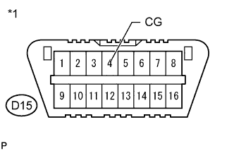
Text in Illustration*1
| Front view of DLC3
|
Measure the voltage according to the value(s) in the table below.
- Standard Voltage:
Tester Connection
| Switch Condition
| Specified Condition
|
D15-13 (TC) - D15-4 (CG)
| Ignition switch ON
| 11 to 14 V
|
ResultResult
| Proceed to
|
NG
| A
|
OK
| B
|
| 3.CHECK HARNESS AND CONNECTOR (TC of DLC3 - ECM) |
Turn the ignition switch off.
Disconnect the ECM connector.
Measure the resistance according to the value(s) in the table below.
- Standard Resistance:
Tester Connection
| Condition
| Specified Condition
|
D15-13 (TC) - A21-27 (TC)
| Always
| Below 1 Ω
|
D15-13 (TC) - Body ground
| Always
| 10 kΩ or higher
|
| | REPAIR OR REPLACE HARNESS OR CONNECTOR |
|
|
| 4.CHECK HARNESS AND CONNECTOR (CG of DLC3 - BODY GROUND) |
Measure the resistance according to the value(s) in the table below.
Text in Illustration*1
| Front view of DLC3
|
- Standard Resistance:
Tester Connection
| Condition
| Specified Condition
|
D15-4 (CG) - Body ground
| Always
| Below 1 Ω
|
| | REPAIR OR REPLACE HARNESS OR CONNECTOR |
|
|
| 5.INSPECT ECM (TC of DLC3 INPUT) |
Turn the ignition switch off.
Text in Illustration*1
| Front view of DLC3
|
Reconnect the ECM connector.
Using SST, connect terminals TC and CG of the DLC3.
Turn the ignition switch to ON.
Check that the check engine warning light is blinking.
ResultResult
| Proceed to
|
Check engine warning light is blinking
| A
|
Check engine warning light is not blinking
| B
|
| | REPAIR OR REPLACE WIRE HARNESS OR ECM (TC of ECM CIRCUIT) |
|
|