Dtc P0037 Oxygen Sensor Heater Control Circuit Low (Bank 1 Sensor 2)
DESCRIPTION
MONITOR DESCRIPTION
MONITOR STRATEGY
TYPICAL ENABLING CONDITIONS
TYPICAL MALFUNCTION THRESHOLDS
COMPONENT OPERATING RANGE
MONITOR RESULT
CONFIRMATION DRIVING PATTERN
WIRING DIAGRAM
INSPECTION PROCEDURE
INSPECT HEATED OXYGEN SENSOR (HEATER RESISTANCE)
CHECK TERMINAL VOLTAGE (+B OF HO2 SENSOR)
INSPECT INTEGRATION RELAY (EFI RELAY)
CHECK HARNESS AND CONNECTOR (HO2 SENSOR - EFI RELAY)
CHECK HARNESS AND CONNECTOR (HO2 SENSOR - ECM)
CHECK WHETHER DTC OUTPUT RECURS (DTC P0037, P0038 AND/OR P0141)
DTC P0037 Oxygen Sensor Heater Control Circuit Low (Bank 1 Sensor 2) |
DTC P0038 Oxygen Sensor Heater Control Circuit High (Bank 1 Sensor 2) |
DTC P0141 Oxygen Sensor Heater Circuit Malfunction (Bank 1 Sensor 2) |
DESCRIPTION
- Refer to DTC P0136 (YARIS_NCP93 RM000000TEO09JX_01.html).
- HINT:
- Sensor 2 refers to the sensor mounted behind the Three-Way Catalytic Converter (TWC) and located far from the engine assembly.
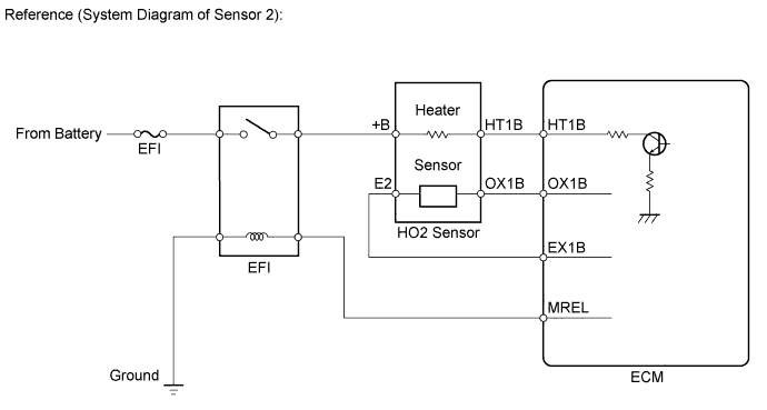
- When any of these DTCs are stored, the ECM enters fail-safe mode. The ECM turns off the Heated Oxygen (HO2) Sensor heater in fail-safe mode. Fail-safe mode continues until the ignition switch is turned to OFF.
- The ECM provides a pulse width modulated control circuit to adjust the current through the heater. The HO2 sensor heater circuit uses a relay on the +B side of the circuit.
DTC No.
| DTC Detection Condition
| Trouble Area
|
P0037
| Heated Oxygen (HO2) sensor heater current less than 0.3 A
(1 trip detection logic)
| - Open in HO2 sensor heater circuit
- HO2 sensor heater (sensor 2)
- Integration relay (EFI relay)
- ECM
|
P0038
| Heated Oxygen (HO2) sensor heater current 2 A or more
(1 trip detection logic)
| - Short in HO2 sensor heater circuit
- HO2 sensor heater (sensor 2)
- Integration relay (EFI relay)
- ECM
|
P0141
| Cumulative heater resistance correction value exceeds threshold
(2 trip detection logic)
| - Open or short in HO2 sensor heater circuit
- HO2 sensor heater (sensor 2)
- Integration relay (EFI relay)
- ECM
|
MONITOR DESCRIPTION
The sensing portion of the Heated Oxygen (HO2) sensor has a zirconia element which is used to detect the oxygen concentration in the exhaust gas. If the zirconia element is at the appropriate temperature, and the difference between the oxygen concentrations surrounding the inside and outside surfaces of the sensor is large, the zirconia element generates voltage signals. In order to increase the oxygen concentration detecting capacity of the zirconia element, the ECM supplements the heat from the exhaust with heat from a heating element inside the sensor.- Heated oxygen sensor heater range check (P0037 and P0038):
The ECM monitors the current applied to the HO2 sensor heater to check the heater for malfunctions. If the current is below the threshold value, the ECM determines that there is an open circuit in the heater. If the current is above the threshold value, the ECM determines that there is a short circuit in the heater.
The ECM constantly monitors the current applied to the heater. If the ECM detects an open or short circuit, the ECM turns the MIL on and stores a DTC.
If a malfunction is detected, the ECM cuts off the current applied to the heater.
Example:
The ECM stores DTC P0038 when the current in the HO2 sensor heater is more than 2 A. Conversely, when the heater current is less than 0.3 A, DTC P0037 is stored.
- Heated oxygen sensor heater performance (P0141):
After the accumulated heater ON time exceeds 100 seconds, the ECM calculates the heater resistance using the battery voltage and the current applied to the heater.
If the resistance is above the threshold value, the ECM determines that there is a malfunction in the HO2 sensor heater and stores DTC P0141.
MONITOR STRATEGY
Related DTCs
| P0037: Heated oxygen sensor heater range check (Low electrical current)
P0038: Heated oxygen sensor heater range check (High electrical current)
P0141: Heated oxygen sensor heater performance
|
Required Sensors/Components (Main)
| Heated oxygen sensor heater
|
Required Sensors/Components (Related)
| -
|
Frequency of Operation
| Continuous: P0037 and P0038
Once per driving cycle: P0141
|
Duration
| 0.5 seconds: P0037
With in 1 second: P0038
10 seconds: P0141
|
MIL Operation
| Immediate: P0037 and P0038
2 driving cycles: P0141
|
Sequence of Operation
| None
|
TYPICAL ENABLING CONDITIONS
All:Monitor runs whenever following DTCs not present
| None
|
P0037:A. All of the following conditions are met
| -
|
Battery voltage
| 10.5 to 20 V
|
Learned heater OFF current operation
| Complete
|
Active heater OFF control
| Not operating
|
Active heater ON control
| Not operating
|
Oxygen Sensor Heater High current fail (P0032,P0038)
| Not detected
|
B. All of the following conditions are met
| 0.5 seconds or more
|
Heater OFF time
| less than 0.1 second
|
Heater current - Learned heater OFF current
| less than 0.3 A
|
P0038:Battery voltage
| 10.5 to 20 V
|
P0141 (Heater performance monitor check):All of following conditions met:
| -
|
Battery voltage
| 10.5 V or more
|
Fuel cut
| OFF
|
Time after fuel cut ON to OFF
| 30 seconds or more
|
Accumulated heater ON time
| 100 seconds or more
|
Learned heater OFF current operation
| Complete
|
Oxygen Sensor Heater High current fail (P0032,P0038)
| Not detected
|
Oxygen Sensor Heater Low current fail (P0031,P0037)
| Not detected
|
TYPICAL MALFUNCTION THRESHOLDS
P0037:Heater current
| Less than 0.3 A
|
P0038:Heater current
| 2 A or more
|
P0141 (Heater performance monitor check):Accumulated heater resistance
| Varies with sensor element temperature (Example: More than 23 Ω)
|
COMPONENT OPERATING RANGE
Heated Oxygen (HO2) sensor heater current
| 0.4 to 1 A (when engine idles, HO2 sensor warmed up and battery voltage 11 to 14 V)
|
MONITOR RESULT
Refer to Checking Monitor Status (YARIS_NCP93 RM000000PDR0A3X.html).
CONFIRMATION DRIVING PATTERN
- Connect the Techstream to the DLC3.
- Turn the ignition switch to ON and turn the Techstream on.
- Clear DTCs (even if no DTCs are stored, perform the clear DTC operation).
- Turn the ignition switch off and wait for at least 30 seconds.
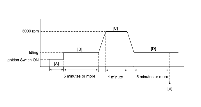
- Turn the ignition switch to ON and turn the Techstream on [A].
- Start the engine and idle it for 5 minutes or more [B].
- With the vehicle stationary, depress the accelerator pedal and maintain an engine speed of 3000 rpm for 1 minute [C].
- Idle the engine for 5 minutes or more [D].
- Enter the following menus: Powertrain / Engine and ECT / Trouble Codes [E].
- Read pending DTCs.
- HINT:
- If a pending DTC is output, the system is malfunctioning.
- If a pending DTC is not output, perform the following procedure.
- Enter the following menus: Powertrain / Engine and ECT / Utility / All Readiness.
- Input the DTC: P0037, P0038 or P0141.
- Check the DTC judgment result.
Techstream Display
| Description
|
NORMAL
| - DTC judgment completed
- System normal
|
ABNORMAL
| - DTC judgment completed
- System abnormal
|
INCOMPLETE
| - DTC judgment not completed
- Perform driving pattern after confirming DTC enabling conditions
|
N/A
| - Unable to perform DTC judgment
- Number of DTCs which do not fulfill DTC preconditions has reached ECU memory limit
|
- HINT:
- If the judgment result shows NORMAL, the system is normal.
- If the judgment result shows ABNORMAL, the system has a malfunction.
- If the judgment result shows INCOMPLETE or N/A, perform steps [B] through [E] again.
- If no pending DTC is output, perform a universal trip and check for permanent DTCs (YARIS_NCP93 RM000000PDK0QGX.html).
- HINT:
- If a permanent DTC is output, the system is malfunctioning.
- If no permanent DTC is output, the system is normal.
WIRING DIAGRAM
Refer to DTC P2195 (YARIS_NCP93 RM000000WC40K6X_07.html).
INSPECTION PROCEDURE
- NOTICE:
- Inspect the fuses for circuits related to this system before performing the following inspection procedure.
- HINT:
- Read freeze frame data using the Techstream. The ECM records vehicle and driving condition information as freeze frame data the moment a DTC is stored. When troubleshooting, freeze frame data can help determine if the vehicle was moving or stationary, if the engine was warmed up or not, if the air fuel ratio was lean or rich, and other data from the time the malfunction occurred.
- When the value for the Data List item O2 Heater Curr Val B1S2 is not 0 A, the heater is on.
- Refer to "Data List / Active Test" [O2 Heater B1S2 and O2 Heater Curr Val B1S2 (YARIS_NCP93 RM000000PDN0J9X.html).
- Sensor 1 refers to the sensor closest to the engine assembly.
- Sensor 2 refers to the sensor farthest away from the engine assembly.
- Change the fuel injection volume using the Control the Injection Volume function provided in the Active Test and monitor the heated oxygen sensor output voltage (YARIS_NCP93 RM000000TEO09JX_10.html). If the sensor output voltage does not change (almost no reaction) while performing the Active Test, the sensor may be malfunctioning.
| 1.INSPECT HEATED OXYGEN SENSOR (HEATER RESISTANCE) |
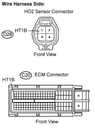
Disconnect the D28 Heated Oxygen (HO2) sensor connector.
Measure the resistance of the HO2 sensor connector.
- Standard resistance:
Tester Connections
| Specified Conditions
|
HT1B (1) - +B (2)
| 11 to 16 Ω at 20°C (68°F)
|
HT1B (1) - E2 (4)
| 10 kΩ or higher
|
Reconnect the HO2 sensor connector.
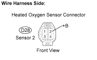
| 2.CHECK TERMINAL VOLTAGE (+B OF HO2 SENSOR) |
Disconnect the D28 HO2 sensor connector.
Measure the voltage between the terminals of the D28 HO2 sensor connector and body ground.
- Standard voltage:
Tester Connections
| Specified Conditions
|
+B (D28-2) - Body ground
| 11 to 14 V
|
ResultResult
| Proceed to
|
NG
| A
|
OK
| B
|
Reconnect the HO2 sensor connector.
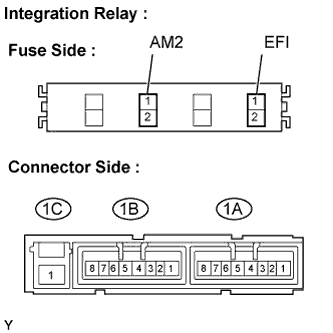
| 3.INSPECT INTEGRATION RELAY (EFI RELAY) |
Remove the integration relay from the engine room relay block.
Inspect the EFI fuse.
Remove the EFI fuse from the integration relay.
Measure the EFI fuse resistance.
- Standard resistance:
- Below 1 Ω
Reinstall the EFI fuse.
Inspect the EFI relay.
Measure the EFI relay resistance.
- Standard resistance:
Tester Connections
| Specified Conditions
|
1C-1 - 1A-4
| 10 kΩ or higher
|
Below 1 Ω
(Apply battery voltage between terminals 1A-2 and 1A-3)
|
Reinstall the integration relay.
| | REPLACE INTEGRATION RELAY |
|
|
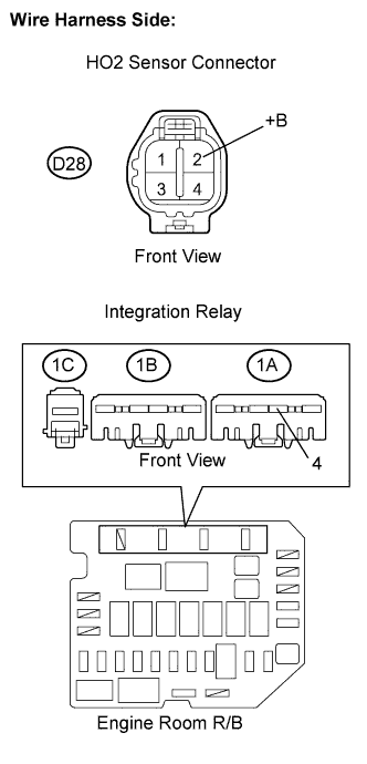
| 4.CHECK HARNESS AND CONNECTOR (HO2 SENSOR - EFI RELAY) |
Disconnect the D28 HO2 sensor connector.
Remove the integration relay from the engine room Relay Block (R/B).
Check the resistance.
- Standard resistance (Check for open):
Tester Connections
| Specified Conditions
|
+B (D28-2) - Engine room R/B (1A-4)
| Below 1 Ω
|
- Standard resistance (Check for short):
Tester Connections
| Specified Conditions
|
+B (D28-2) or Engine room R/B (1A-4) - Body ground
| 10 kΩ or higher
|
Reconnect the HO2 sensor connector.
Reinstall the integration relay.
| | REPAIR OR REPLACE HARNESS OR CONNECTOR |
|
|
| 5.CHECK HARNESS AND CONNECTOR (HO2 SENSOR - ECM) |
Disconnect the D28 HO2 sensor connector.
Disconnect the C20 ECM connector.
Measure the resistance.
- Standard resistance (Check for open):
Tester Connections
| Specified Conditions
|
HT1B (D28-1) - HT1B (C20-47)
| Below 1 Ω
|
- Standard resistance (Check for short):
Tester Connections
| Specified Conditions
|
HT1B (D28-1) or HT1B (C20-47) - Body ground
| 10 kΩ or higher
|
Reconnect the HO2 sensor connector.
Reconnect the ECM connector.
| | REPAIR OR REPLACE HARNESS OR CONNECTOR |
|
|
| 6.CHECK WHETHER DTC OUTPUT RECURS (DTC P0037, P0038 AND/OR P0141) |
Connect the Techstream to the DLC3.
Turn the ignition switch to ON.
Turn the Techstream on.
Clear DTCs (YARIS_NCP93 RM000000PDK0QGX.html).
Drive the vehicle in accordance with the driving pattern described in the Confirmation Driving Pattern.
Read DTCs.
ResultDisplay (DTC Output)
| Proceed To
|
No output (No pending DTC output)
| A
|
P0037, P0038 and/or P0141
| B
|