Dtc 5C-40 Camera Picture Error
Navigation. Toyota Rav4. Aca30, 33, 38 Gsa33 Zsa30, 35
DESCRIPTION
WIRING DIAGRAM
INSPECTION PROCEDURE
CHECK NAVIGATION RECEIVER ASSEMBLY
CHECK NAVIGATION RECEIVER ASSEMBLY (DISPLAY SIGNAL)
CHECK HARNESS AND CONNECTOR (NAVIGATION RECEIVER - TELEVISION CAMERA)
DTC 5C-40 Camera Picture Error |
DESCRIPTION
DTC Code
| DTC Detection Condition
| Trouble Area
|
5C-40
| Synchronous signal from camera cannot be transmitted..
| - Harness or connector
- Television camera assembly
- Navigation receiver assembly
|
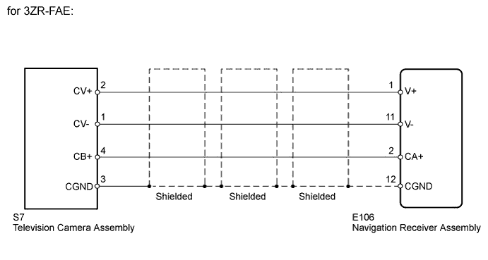
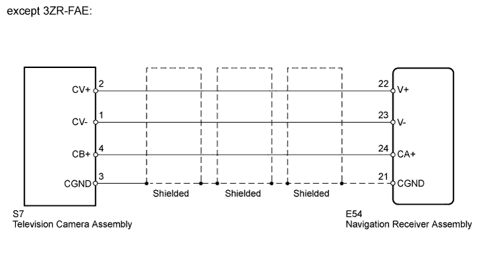
WIRING DIAGRAM
INSPECTION PROCEDURE
| 1.CHECK NAVIGATION RECEIVER ASSEMBLY |
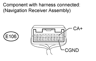
for 3ZR-FAE:
Measure the voltage according to the value(s) in the table below.
- Standard Voltage:
Tester Connection
| Condition
| Specified Condition
|
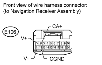
E106-2 (CA+) - E106-12 (CGND)
| Ignition switch ON, shift lever in R
| 5.8 to 6.2 V
|
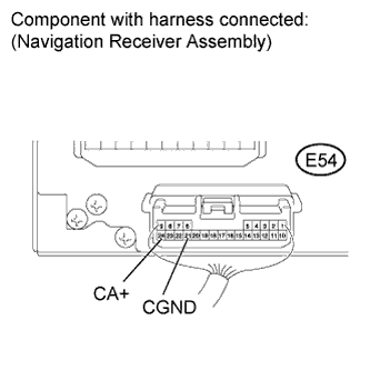
except 3ZR-FAE:
Measure the voltage according to the value(s) in the table below.
- Standard Voltage:
Tester Connection
| Condition
| Specified Condition
|
E54-24 (CA+) - E54-21 (CGND)
| Ignition switch ON, shift lever in R
| 5.8 to 6.2 V
|
| 2.CHECK NAVIGATION RECEIVER ASSEMBLY (DISPLAY SIGNAL) |
for 3ZR-FAE:
Using an oscilloscope, check the waveform.
Measurement ConditionItem
| Content
|
Tester Connection
| E106-1 (V+) - E106-11 (V-)
|
Tool Setting
| 0.2 V/DIV., 50 μs/DIV.
|
Condition
| - Ignition switch ON, shift lever in R*1
- Ignition switch ON, shift lever in R, screen is blacked out by covering camera lens*2
|
- OK:
- Waveform is as shown in illustration.
except 3ZR-FAE:
Using an oscilloscope, check the waveform.
Measurement ConditionItem
| Content
|
Tester Connection
| E54-22 (V+) - E54-23 (V-)
|
Tool Setting
| 0.2 V/DIV., 50 μs/DIV.
|
Condition
| - Ignition switch ON, shift lever in R*1
- Ignition switch ON, shift lever in R, screen is blacked out by covering camera lens*2
|
- OK:
- Waveform is as shown in illustration.
| 3.CHECK HARNESS AND CONNECTOR (NAVIGATION RECEIVER - TELEVISION CAMERA) |
for 3ZR-FAE:
Disconnect the E106 navigation receiver assembly connector.
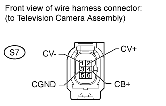
Disconnect the S7 television camera assembly connector.
Measure the resistance according to the value(s) in the table below.
- Standard Resistance:
Tester Connection
| Condition
| Specified Condition
|
E106-1 (V+) - S7-2 (CV+)
| Always
| Below 1 Ω
|
E106-2 (CA+) - S7-4 (CB+)
| Always
| Below 1 Ω
|
E106-11 (V-) - S7-1 (CV-)
| Always
| Below 1 Ω
|
E106-12 (CGND) - S7-3 (CGND)
| Always
| Below 1 Ω
|
E106-1 (V+) - Body ground
| Always
| 10 kΩ or higher
|
E106-2 (CA+) - Body ground
| Always
| 10 kΩ or higher
|
E106-11 (V-) - Body ground
| Always
| 10 kΩ or higher
|
E106-12 (CGND) - Body ground
| Always
| 10 kΩ or higher
|
except 3ZR-FAE:
Disconnect the E54 navigation receiver assembly connector.
Disconnect the S7 television camera assembly connector.
Measure the resistance according to the value(s) in the table below.
- Standard Resistance:
Tester Connection
| Condition
| Specified Condition
|
E54-22 (V+) - S7-2 (CV+)
| Always
| Below 1 Ω
|
E54-24 (CA+) - S7-4 (CB+)
| Always
| Below 1 Ω
|
E54-21 (CGND) - S7-1 (CV-)
| Always
| Below 1 Ω
|
E54-23 (V-) - S7-3 (CGND)
| Always
| Below 1 Ω
|
E54-22 (V+) - Body ground
| Always
| 10 kΩ or higher
|
E54-24 (CA+) - Body ground
| Always
| 10 kΩ or higher
|
E54-21 (CGND) - Body ground
| Always
| 10 kΩ or higher
|
E54-23 (V-) - Body ground
| Always
| 10 kΩ or higher
|
| | REPAIR OR REPLACE HARNESS OR CONNECTOR |
|
|