Navigation System (For Hdd) Microphone Circuit Between Microphone And Navigation Receiver Assembly
Navigation. Toyota Rav4. Aca30, 33, 38 Gsa33 Zsa30, 35
DESCRIPTION
WIRING DIAGRAM
INSPECTION PROCEDURE
INSPECT NAVIGATION RECEIVER ASSEMBLY
CHECK HARNESS AND CONNECTOR (NAVIGATION RECEIVER - MAP LIGHT)
REPLACE TELEPHONE MICROPHONE WITH ANOTHER AND CHECK
NAVIGATION SYSTEM (for HDD) - Microphone Circuit between Microphone and Navigation Receiver Assembly |
DESCRIPTION
This circuit sends a microphone signal from the telephone microphone assembly to the navigation receiver assembly.It also supplies power from the navigation receiver assembly to the telephone microphone assembly.
WIRING DIAGRAM
INSPECTION PROCEDURE
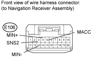
| 1.INSPECT NAVIGATION RECEIVER ASSEMBLY |
Disconnect the E106 navigation receiver assembly connector.
Measure the resistance according to the value(s) in the table below.
- Standard Resistance:
Tester Connection
| Switch Condition
| Specified Condition
|
13 (MIN-) - Body ground
| Always
| Below 1 Ω
|
Measure the voltage according to the value(s) in the table below.
- Standard Voltage:
Tester Connection
| Switch Condition
| Specified Condition
|
5 (MACC) - Body ground
| Ignition switch ACC
| 4.75 to 5.25 V
|
| 2.CHECK HARNESS AND CONNECTOR (NAVIGATION RECEIVER - MAP LIGHT) |
Disconnect the E106 navigation receiver assembly connector.
Disconnect the R8 map light assembly connector.
Measure the resistance according to the value(s) in the table below.
- Standard Resistance:
Tester Connection
| Condition
| Specified Condition
|
E106-5 (MACC) - R8-12 (ACC)
| Always
| Below 1 Ω
|
E106-4 (MIN+) - R8-11 (MI1+)
| Always
| Below 1 Ω
|
E106-13 (MIN-) - R8-10 (MIC-)
| Always
| Below 1 Ω
|
E106-5 (MACC) - Body ground
| Always
| 10 kΩ or higher
|
E106-4 (MIN+) - Body ground
| Always
| 10 kΩ or higher
|
E106-13 (MIN-) - Body ground
| Always
| 10 kΩ or higher
|
E106-3 (SNS2) - Body ground
| Always
| Below 1 Ω
|
| | REPAIR OR REPLACE HARNESS OR CONNECTOR |
|
|
| 3.REPLACE TELEPHONE MICROPHONE WITH ANOTHER AND CHECK |
Replace the telephone microphone with a normal one (RAV4_ACA30 RM0000021PU001X.html).
Check if the same problem occurs again.
| OK |
|
|
|
| END (TELEPHONE MICROPHONE IS FAULTY) |
|