Dtc P1047 Valvematic Driver Learned Value Error / Power Source Circuit Malfunction Bank 1
Engine. Toyota Rav4. Aca30, 33, 38 Gsa33 Zsa30, 35
DESCRIPTION
WIRING DIAGRAM
INSPECTION PROCEDURE
PERFORM SIMULATION TEST
CHECK ANY OTHER DTCS OUTPUT
CHECK CONTINUOUSLY VARIABLE VALVE LIFT CONTROLLER ASSEMBLY (POWER SOURCE)
DTC P1047 Valvematic Driver Learned Value Error / Power Source Circuit Malfunction Bank 1 |
DESCRIPTION
The valve lift control driver in the continuously variable valve lift controller assembly learns and stores the actuator position in memory. If the actuator position learned value is abnormal or cannot be learned due to a continuously variable valve lift controller assembly power supply problem or similar malfunction, DTC P1047 is stored. Also, when a VALVEMATIC system malfunction is detected, the power supply to the continuously variable valve lift controller assembly is cut as a fail-safe function and DTC P1047 is stored.DTC No.
| DTC Detection Condition
| Trouble Area
|
P1047
| The power supply to the continuously variable valve lift controller assembly is cut and the continuously variable valve lift controller internal valve lift control driver actuator position learned value cannot be learned or is abnormal (1 trip detection logic).
| - Continuously variable valve lift controller power source circuit
- Continuously variable valve lift controller assembly
|
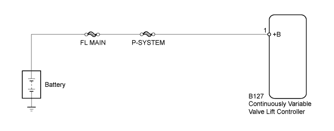
WIRING DIAGRAM
INSPECTION PROCEDURE
- NOTICE:
- When one of the following DTCs is stored and the MIL is illuminated, DTC P1047 is stored and actuator position learning is performed every time the engine is started. Also, after the system returns to normal, the following occurs during the first driving cycle: 1) DTC P1047 is stored, 2) actuator position learning is performed and 3) the MIL illuminates during actuator position learning.
Actuator position learning is performed when these DTCs are stored.
|
P1046, P1049, P104A, P1055, P2646, P2647, P2648, P2649, P264A, U011B
|
- HINT:
- When there is no power (+B) supplied to the continuously variable valve lift controller assembly, DTC U011B is stored. After the continuously variable valve lift controller assembly power supply system and communication lines have been connected or repaired, actuator position learning is performed and DTC P1047 is stored the next time the vehicle is driven.
- After performing repairs, perform the following procedures and check that DTCs are not output again.
- Connect the intelligent tester to the DLC3.
- Start the engine and warm it up.
- Turn the tester on.
- Clear the DTCs.
- Turn the ignition switch off and wait 10 seconds.
- Start the engine and idle it for 20 seconds.
- Clear the DTCs.
- Turn the ignition switch off and wait 10 seconds.
- Start the engine and idle it for 20 seconds.
- Turn the ignition switch off and wait 10 seconds.
- Turn the ignition switch to ON.
- Enter the following menus: Powertrain / Engine and ECT / DTC.
- Read the DTCs.
- NOTICE:
- Inspect the fuses for circuits related to this system before performing the following inspection procedure.
| 1.PERFORM SIMULATION TEST |
Perform a simulation test.
Connect the intelligent tester to the DLC3.
Stop the engine and wait 10 seconds.
Start the engine and idle it for 20 seconds.
Stop the engine and wait 10 seconds.
Turn the ignition switch to ON.
Turn the tester on.
Clear the DTCs (RAV4_ACA30 RM000000PDK0BLX.html).
Start the engine and idle it for 20 seconds.
Check if the MIL is illuminated during idling after clearing the DTCs in the above simulation test.
ResultResult
| Proceed to
|
MIL illuminates
| A
|
MIL does not illuminate
| B
|
- HINT:
- If the ignition switch is turned to ON while the actuator position learning is incomplete or when learning has not been performed, DTC P1047 is output.
| 2.CHECK ANY OTHER DTCS OUTPUT |
Connect the intelligent tester to the DLC3.
Turn the ignition switch to ON.
Turn the intelligent tester on.
Enter the following menus: Powertrain / Engine and ECT / DTC.
Read the DTCs.
ResultResult
| Proceed to
|
DTC P1047 is output
| A
|
DTC P1047 and other DTCs are output
| B
|
| 3.CHECK CONTINUOUSLY VARIABLE VALVE LIFT CONTROLLER ASSEMBLY (POWER SOURCE) |
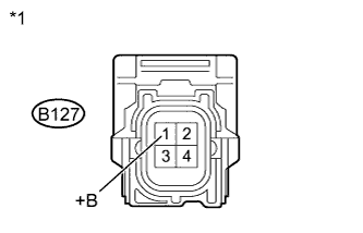
Disconnect the continuously variable valve lift controller assembly connector.
Measure the voltage according to the value(s) in the table below.
- Standard Voltage:
Tester Connection
| Switch Condition
| Specified Condition
|
B127-1 (+B) - Body ground
| Ignition switch ON
| 11 to 14 V
|
Text in Illustration*1
| Front view of wire harness connector
(to Continuously Variable Valve Lift Controller)
|
| | REPAIR OR REPLACE HARNESS OR CONNECTOR (CONTINUOUSLY VARIABLE VALVE LIFT CONTROLLER - BATTERY) |
|
|