Camshaft (For Bank 1) Removal
Engine. Toyota Rav4. Aca30, 33, 38 Gsa33 Zsa30, 35
REMOVE ENGINE WITH TRANSAXLE
REMOVE FRONT CROSS MEMBER SUB-ASSEMBLY
REMOVE FRONT SUSPENSION CROSSMEMBER SUB-ASSEMBLY
REMOVE ENGINE WIRE
REMOVE STARTER ASSEMBLY
REMOVE AUTOMATIC TRANSAXLE ASSEMBLY
REMOVE TRANSFER ASSEMBLY
REMOVE DRIVE PLATE AND RING GEAR SUB-ASSEMBLY
INSTALL ENGINE TO ENGINE STAND
REMOVE INTAKE AIR SURGE TANK ASSEMBLY
REMOVE IGNITION COIL ASSEMBLY
REMOVE NO. 2 ENGINE MOUNTING STAY RH
REMOVE INTAKE MANIFOLD
REMOVE MANIFOLD STAY
REMOVE EXHAUST MANIFOLD SUB-ASSEMBLY RH
REMOVE V-RIBBED BELT
REMOVE NO. 2 IDLER PULLEY SUB-ASSEMBLY
REMOVE COOLER COMPRESSOR ASSEMBLY
REMOVE GENERATOR ASSEMBLY
REMOVE OIL DIPSTICK GUIDE
REMOVE NO. 2 MANIFOLD STAY
REMOVE NO. 2 EXHAUST MANIFOLD HEAT INSULATOR
REMOVE EXHAUST MANIFOLD SUB-ASSEMBLY LH
REMOVE V-RIBBED BELT TENSIONER ASSEMBLY
REMOVE NO. 2 TIMING GEAR COVER
REMOVE WATER PUMP PULLEY
REMOVE RADIO SETTING CONDENSER
REMOVE NO. 1 VACUUM SWITCHING VALVE ASSEMBLY
REMOVE CRANKSHAFT PULLEY
REMOVE WATER INLET HOUSING
REMOVE NO. 2 OIL PAN SUB-ASSEMBLY
REMOVE OIL STRAINER SUB-ASSEMBLY
REMOVE OIL PAN SUB-ASSEMBLY
REMOVE NO. 1 OIL PIPE
REMOVE OIL PIPE
REMOVE CYLINDER HEAD COVER SUB-ASSEMBLY (for Bank 1)
REMOVE CYLINDER HEAD COVER SUB-ASSEMBLY (for Bank 2)
REMOVE TIMING CHAIN COVER SUB-ASSEMBLY
REMOVE TIMING CHAIN COVER OIL SEAL
SET NO. 1 CYLINDER TO TDC / COMPRESSION
REMOVE NO. 1 CHAIN TENSIONER ASSEMBLY
REMOVE CHAIN TENSIONER SLIPPER
REMOVE NO. 1 CHAIN SUB-ASSEMBLY
REMOVE IDLE SPROCKET ASSEMBLY
REMOVE CAMSHAFT TIMING GEARS AND NO. 2 CHAIN (for Bank 1)
REMOVE NO. 2 CHAIN TENSIONER ASSEMBLY
REMOVE CAMSHAFT BEARING CAP (for Bank 1)
REMOVE NO. 1 CAMSHAFT
REMOVE NO. 2 CAMSHAFT
REMOVE CAMSHAFT HOUSING SUB-ASSEMBLY (for Bank 1)
Camshaft (For Bank 1) -- Removal |
| 1. REMOVE ENGINE WITH TRANSAXLE |
Remove the engine with transaxle (RAV4_ACA30 RM0000019Y9015X.html)
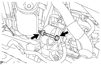
| 2. REMOVE FRONT CROSS MEMBER SUB-ASSEMBLY |
Remove the bolt, nut and crossmember.
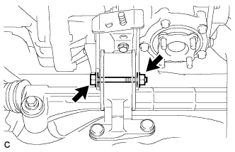
| 3. REMOVE FRONT SUSPENSION CROSSMEMBER SUB-ASSEMBLY |
Remove the bolt and suspension crossmember.
Remove the engine wire from the engine.
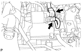
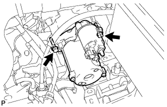
| 5. REMOVE STARTER ASSEMBLY |
Disconnect the starter connector.
Open the terminal cap, remove the nut and disconnect the starter wire.
Remove the 2 bolts and starter.
| 6. REMOVE AUTOMATIC TRANSAXLE ASSEMBLY |
Remove the 2 bolts and flywheel housing under cover.
Turn the crankshaft to gain access and remove the 6 bolts while holding the crankshaft pulley bolt with a wrench.
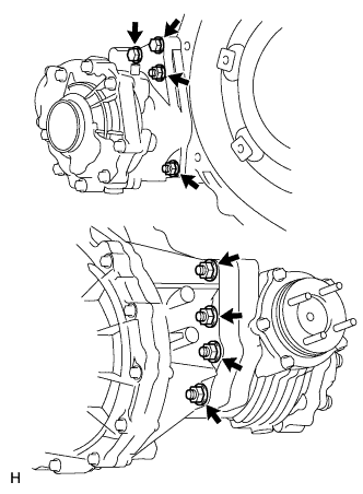
Remove the 3 lower side mounting bolts.
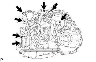
Remove the 7 upper side mounting bolts.
Separate and remove the automatic transaxle.
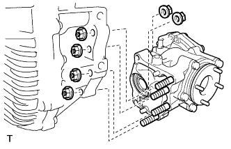
| 7. REMOVE TRANSFER ASSEMBLY |
except K111F:
Remove the 6 nuts, 2 bolts and transfer from the transaxle.
for K111F:
Remove the 6 nuts and transfer from the transaxle.
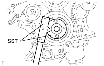
| 8. REMOVE DRIVE PLATE AND RING GEAR SUB-ASSEMBLY |
Using SST, hold the crankshaft.
- SST
- 09213-70011(09213-70020)
09330-00021
Remove the 8 bolts, front spacer, drive plate and rear spacer.
- NOTICE:
- Do not reuse the bolts.
| 9. INSTALL ENGINE TO ENGINE STAND |
Install the engine to an engine stand. Remove the sling device and chain block from the engine.
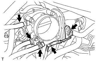
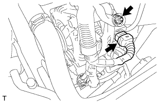
| 10. REMOVE INTAKE AIR SURGE TANK ASSEMBLY |
Disconnect the 2 water by-pass hoses from the throttle body.
Disconnect the vapor feed hose.
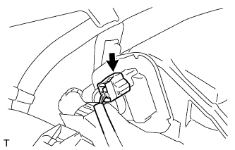
Disconnect the throttle body connector and clamp.
Disconnect the connector.
Disconnect the No. 1 ventilation hose and vacuum hose.
Remove the 2 bolts and throttle body bracket.
Remove the 2 bolts and No. 1 surge tank stay.
Using a 5 mm socket hexagon wrench, remove the 4 bolts.
Remove the 2 nuts and surge tank.
Remove the gasket from the surge tank.
| 11. REMOVE IGNITION COIL ASSEMBLY |
Remove the 6 bolts and 6 coils from the cylinder head.
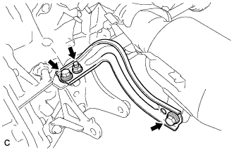
| 12. REMOVE NO. 2 ENGINE MOUNTING STAY RH |
Remove the bolt and mounting stay.
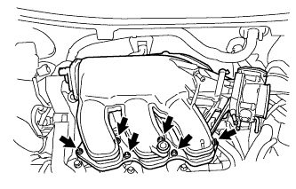
| 13. REMOVE INTAKE MANIFOLD |
Remove the 6 bolts, 4 nuts, intake manifold and 2 gaskets.
Remove the 2 bolts, nut and manifold stay.
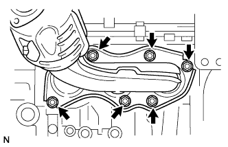
| 15. REMOVE EXHAUST MANIFOLD SUB-ASSEMBLY RH |
Disconnect the air fuel ratio sensor connector clamp.
Uniformly loosen and remove the 6 nuts.
Remove the manifold and gasket.
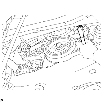
Rotate the tensioner pulley counterclockwise to loosen the belt tension. Then remove the V-ribbed belt.
While turning the belt tensioner counterclockwise, align its holes, and then insert a 5 mm bi-hexagon wrench into the holes to fix the V-ribbed belt tensioner in place.
| 17. REMOVE NO. 2 IDLER PULLEY SUB-ASSEMBLY |
Remove the bolt, No. 2 idler pulley cover plate, idler pulley and idler pulley cover plate.
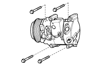
| 18. REMOVE COOLER COMPRESSOR ASSEMBLY |
Disconnect the connector.
Remove the 4 bolts and cooler compressor.
| 19. REMOVE GENERATOR ASSEMBLY |
Disconnect the 2 wire harness clamps.
Remove the terminal cap.
Remove the nut and disconnect the generator wire from terminal B.
Disconnect the generator connector from the generator.
Remove the bolt from the cylinder block.
Remove the 2 bolts and generator.
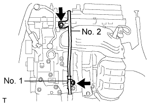
| 20. REMOVE OIL DIPSTICK GUIDE |
Remove the dipstick.
Remove the 2 bolts, and the No. 1 and No. 2 guides.
Remove the O-rings from the guide.
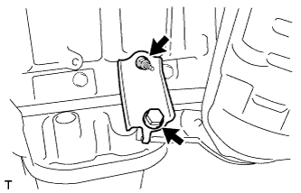
| 21. REMOVE NO. 2 MANIFOLD STAY |
Remove the bolt, nut and manifold stay.
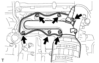
| 22. REMOVE NO. 2 EXHAUST MANIFOLD HEAT INSULATOR |
Remove the 3 bolts and insulator.
| 23. REMOVE EXHAUST MANIFOLD SUB-ASSEMBLY LH |
Uniformly loosen and remove the 6 nuts.
Remove the manifold and gasket.
| 24. REMOVE V-RIBBED BELT TENSIONER ASSEMBLY |
Remove the 5 bolts and V-ribbed belt tensioner assembly.
| 25. REMOVE NO. 2 TIMING GEAR COVER |
Remove the 2 bolts and gear cover.
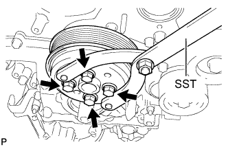
| 26. REMOVE WATER PUMP PULLEY |
Using SST, hold the water pump pulley.
- SST
- 09960-10010(09962-01000,09963-00700)
Remove the 4 bolts and water pump pulley.
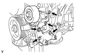
| 27. REMOVE RADIO SETTING CONDENSER |
Remove the 2 bolts and 2 radio setting condensers.
| 28. REMOVE NO. 1 VACUUM SWITCHING VALVE ASSEMBLY |
Remove the bolt and No. 1 vacuum switching valve.
| 29. REMOVE CRANKSHAFT PULLEY |
Using SST, hold the crankshaft pulley and loosen the pulley bolt. Continue to loosen the bolt until only 2 or 3 threads are screwed into the crankshaft.
- SST
- 09213-70011(09213-70020)
09330-00021
Using the pulley set bolt and SST, remove the crankshaft pulley and pulley bolt.
- SST
- 09950-50013(09951-05010,09952-05010,09953-05020,09954-05021)
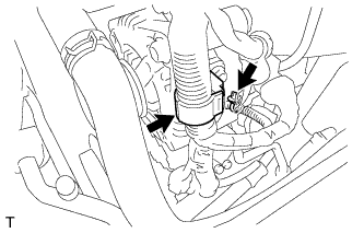
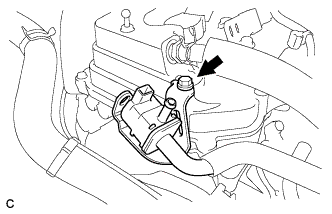
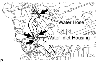
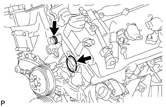
| 30. REMOVE WATER INLET HOUSING |
Disconnect the water hose.
Remove the 2 bolts, nut and water inlet housing.
Remove the water inlet housing No. 1 gasket and water outlet pipe O-ring.
| 31. REMOVE NO. 2 OIL PAN SUB-ASSEMBLY |
Remove the 16 bolts and 2 nuts.
Insert the blade of an oil pan seal cutter between the oil pans, cut through the applied sealer and remove the oil pan.
- NOTICE:
- Be careful not to damage the contact surfaces of the oil pans.
| 32. REMOVE OIL STRAINER SUB-ASSEMBLY |
Remove the bolt, 2 nuts, oil strainer and gasket.
| 33. REMOVE OIL PAN SUB-ASSEMBLY |
Remove the 16 bolts and 2 nuts.
- HINT:
- Be sure to clean the bolts and stud bolts and check the threads for cracks or other damage.
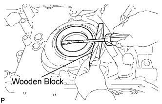
Remove the oil pan by prying between the oil pan and cylinder block with a screwdriver.
- NOTICE:
- Be careful not to damage the contact surfaces of the cylinder block and oil pan.
- HINT:
- Tape the screwdriver tip before use.
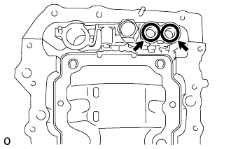
Remove the 2 O-rings from the oil pump.
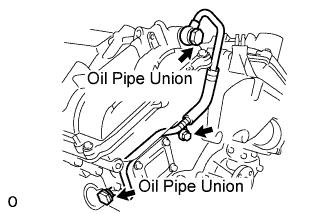
| 34. REMOVE NO. 1 OIL PIPE |
Remove the 2 oil pipe unions, gaskets and oil pipe.
Remove the oil control valve filter LH and gaskets.
Remove the bolt.
Remove the 2 oil pipe unions and oil pipe.
Remove the oil control valve filter RH and gaskets.
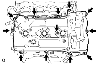
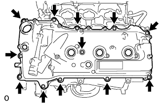
| 36. REMOVE CYLINDER HEAD COVER SUB-ASSEMBLY (for Bank 1) |
Remove the 12 bolts, cylinder head cover and gasket.
- HINT:
- Make sure the removed parts are returned to the same locations they were removed from.
| 37. REMOVE CYLINDER HEAD COVER SUB-ASSEMBLY (for Bank 2) |
Remove the 12 bolts, cylinder head cover and gasket.
- HINT:
- Make sure the removed parts are returned to the same locations they were removed from.
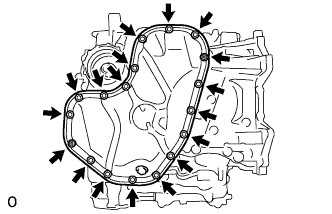
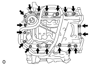
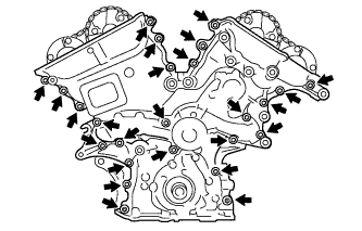
| 38. REMOVE TIMING CHAIN COVER SUB-ASSEMBLY |
Remove the 23 bolts and 2 nuts as shown in the illustration.
Remove the timing chain cover by prying between the timing chain cover and cylinder head or cylinder block with a screwdriver.
- HINT:
- Tape the screwdriver tip before use.
- NOTICE:
- Do not damage the contact surfaces of the cylinder head, cylinder block and timing chain cover.
Remove the gasket.
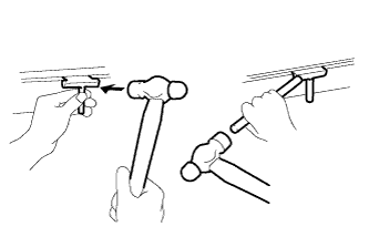
| 39. REMOVE TIMING CHAIN COVER OIL SEAL |
Using a screwdriver, pry out the oil seal.
- HINT:
- Tape the screwdriver tip before use.
- NOTICE:
- Do not damage the surface of the oil seal press fit hole.
Using SST and a hammer, tap in a new oil seal until its surface is flush with the timing chain cover edge.
- SST
- 09316-60011(09316-00011)
- NOTICE:
- Keep the lip free from foreign matter.
- Do not tap the oil seal at an angle.
- Make sure that the oil seal edge does not stick out of the timing chain case.
Apply MP grease to the lip of the oil seal.
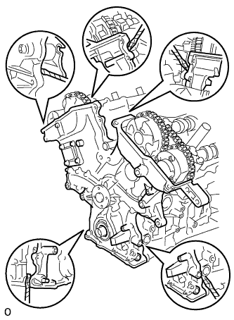
| 40. SET NO. 1 CYLINDER TO TDC / COMPRESSION |
Temporarily tighten the pulley set bolt.
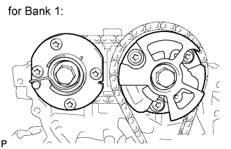
Set the timing mark on the crank angle sensor plate to the RH block bore center line (TDC / compression).
Check that the timing marks of the camshaft timing gears are aligned with the timing marks of the bearing cap as shown in the illustration. If not, turn the crankshaft 1 revolution (360°) and align the timing marks as in the previous step.
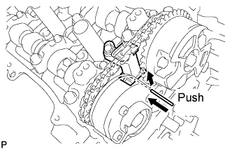
| 41. REMOVE NO. 1 CHAIN TENSIONER ASSEMBLY |
Move the stopper plate upward to release the lock, and push the plunger deep into the tensioner.
Move the stopper plate downward to set the lock, and insert a hexagon wrench into the stopper plate hole.
Remove the 2 bolts and chain tensioner.
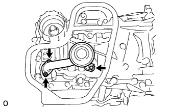
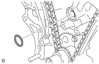
| 42. REMOVE CHAIN TENSIONER SLIPPER |
| 43. REMOVE NO. 1 CHAIN SUB-ASSEMBLY |
Turn the crankshaft counterclockwise 10° to loosen the chain of the crankshaft timing gear.
Remove the chain from the crankshaft timing gear and place it on the crankshaft.
Turn the camshaft timing gear on the RH bank clockwise (approximately 60°) and set it as shown in the illustration. Be sure to loosen the chain between the center banks.
Remove the chain.
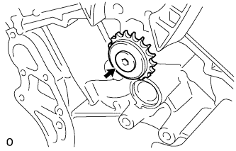
| 44. REMOVE IDLE SPROCKET ASSEMBLY |
Using a 10 mm hexagon wrench, remove the No. 2 idle gear shaft, idle sprocket and No. 1 idle gear shaft.
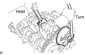
| 45. REMOVE CAMSHAFT TIMING GEARS AND NO. 2 CHAIN (for Bank 1) |
While raising up the No. 2 chain tensioner, insert a pin of φ1.0 mm (0.039 in.) into the hole to fix it in place.
Hold the hexagonal portion of the camshaft with a wrench, and remove the 2 bolts and 2 camshaft timing gears.
- NOTICE:
- Be careful not to damage the cylinder head with the wrench.
- Do not disassemble the camshaft timing gear.
Remove the No. 2 chain.
| 46. REMOVE NO. 2 CHAIN TENSIONER ASSEMBLY |
Remove the bolt and chain tensioner.
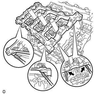
| 47. REMOVE CAMSHAFT BEARING CAP (for Bank 1) |
Remove the 3 gaskets.
Make sure that the knock pin of the camshaft is positioned as shown in the illustration.
Uniformly loosen and remove the 8 bearing cap bolts in several steps and in the sequence shown in the illustration.
Uniformly loosen and remove the 12 bearing cap bolts in several steps and in the sequence shown in the illustration.
- NOTICE:
- Uniformly loosen the bolts while keeping the camshaft level.
Remove the 5 bearing caps.
| 48. REMOVE NO. 1 CAMSHAFT |
Remove the No. 1 camshaft.
| 49. REMOVE NO. 2 CAMSHAFT |
Remove the No. 2 camshaft.
| 50. REMOVE CAMSHAFT HOUSING SUB-ASSEMBLY (for Bank 1) |
Remove the camshaft housing by prying between the cylinder head and camshaft housing with a screwdriver.
- NOTICE:
- Be careful not to damage the contact surfaces of the cylinder head and camshaft housing.
- HINT:
- Tape the screwdriver tip before use.