Intake Manifold -- Installation |
| 1. INSTALL NO. 1 GAS FILTER |
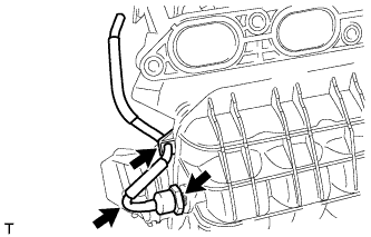 |
Using a 24 mm deep socket wrench, install the gas filter to the intake manifold.
- Torque:
- 17 N*m{173 kgf*cm, 13 ft.*lbf}
Connect the air hose.
| 2. INSTALL INTAKE MANIFOLD |
Using an E6 "TORX" socket wrench, install the 2 stud bolts to the intake manifold.
- Torque:
- 5.0 N*m{51 kgf*cm, 44 in.*lbf}
 |
Install the wire harness clamp bracket to the intake manifold with the bolt.
- Torque:
- 15 N*m{153 kgf*cm, 11 ft.*lbf}
Install a new gasket to the intake manifold.
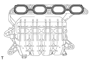 |
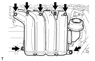
Install the intake manifold and intake manifold stay with the 5 bolts and 2 nuts.
- Torque:
- 28 N*m{286 kgf*cm, 21 ft.*lbf}
 |
Connect the fuel vapor feed hose and ventilation hose.
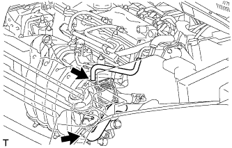 |
Attach the 4 clamps to the intake manifold.
 |
Install the wire harness clamp bracket with the bolt.
- Torque:
- 7.7 N*m{78 kgf*cm, 68 in.*lbf}
| 3. INSTALL ENGINE COVER JOINT |
Install the engine cover joint.
- Torque:
- 8.0 N*m{82 kgf*cm, 71 in.*lbf}
| 4. INSTALL VACUUM SWITCHING VALVE ASSEMBLY (for ACIS) |
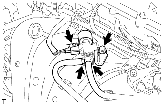 |
Install the vacuum switching valve with the bolt.
- Torque:
- 10 N*m{102 kgf*cm, 7 ft.*lbf}
Connect the connector and 2 vacuum hoses.
| 5. INSTALL VACUUM SENSOR ASSEMBLY |
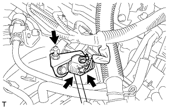 |
Connect the air hose to the vacuum sensor.
Install the vacuum sensor with the engine cover joint.
- Torque:
- 8.0 N*m{82 kgf*cm, 71 in.*lbf}
Connect the vacuum sensor connector.
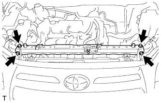
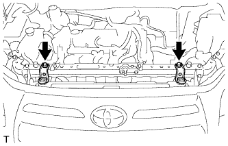
| 6. INSTALL UPPER RADIATOR SUPPORT SUB-ASSEMBLY |
Install the upper radiator support with the 4 bolts.
- Torque:
- 31 N*m{316 kgf*cm, 23 ft.*lbf}
 |
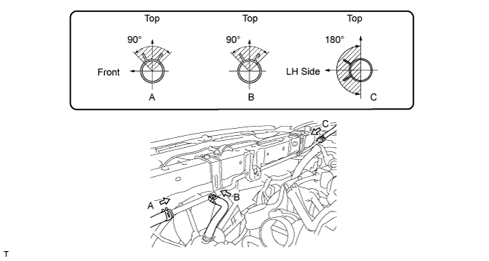
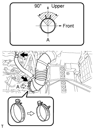
Connect the 3 water by-pass hoses to the No. 1 water by-pass pipe.
- HINT:
- The direction of the hose clamp is indicated in the illustration.
w/ Hood Courtesy Switch:
Attach the wire harness clamp to the upper radiator support.
Attach the clamp to connect the hood lock cable.
| 7. INSTALL UPPER RADIATOR SUPPORT BRACKET |
Install the 2 upper radiator support brackets with the 2 bolts.
- Torque:
- 19 N*m{194 kgf*cm, 14 ft.*lbf}
 |
| 8. INSTALL HOOD LOCK ASSEMBLY |
for LHD:
Install the hood lock (RAV4_ACA30 RM00000138P00MX_01_0002.html).
for RHD:
Install the hood lock (RAV4_ACA30 RM00000138P00NX_01_0002.html).
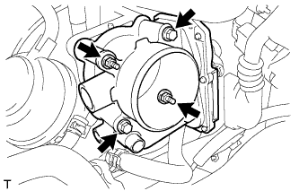
| 9. INSTALL THROTTLE BODY ASSEMBLY |
Install a new gasket into the intake manifold.
Install the throttle body with the 2 bolts and 2 nuts.
- Torque:
- 10 N*m{102 kgf*cm, 7 ft.*lbf}
 |
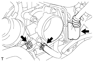
Connect the throttle body connector and 2 water hoses.
 |
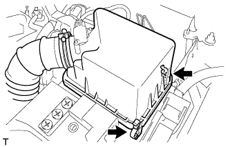
| 10. INSTALL AIR CLEANER CAP SUB-ASSEMBLY |
Insert the hinge part of the air cleaner cap and hose into the air cleaner case, and then fasten the 2 hook clamps.
 |
Connect the No. 1 air cleaner hose to the throttle body and push apart the tabs of the No. 1 air cleaner hose clamp.
- HINT:
- The direction of the hose clamp is indicated in the illustration.
 |
Connect the No. 2 ventilation hose to the cylinder head cover.
Attach the clamp.
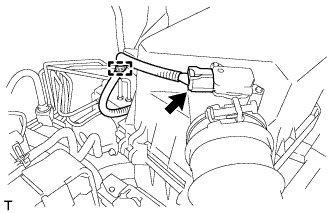 |
Connect the mass air flow meter connector.
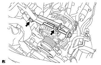
| 11. INSTALL GENERATOR ASSEMBLY |
Install the wire harness clamp bracket with the bolt.
- Torque:
- 8.4 N*m{85 kgf*cm, 74 in.*lbf}
 |
Temporarily install the generator with the bolt.
 |
Temporarily install the adjusting bar with the 2 bolts.
 |
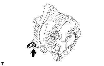
Install the wire harness to terminal B with the nut.
- Torque:
- 9.8 N*m{100 kgf*cm, 87 in.*lbf}
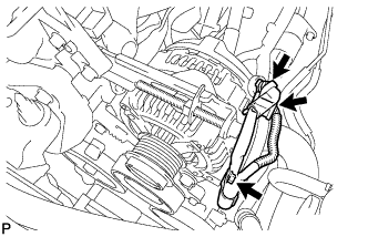 |
Install the terminal cap.
Connect the connector and wire harness clamp.
Install V-ribbed belt (RAV4_ACA30 RM0000027IM00YX_03_0012.html).
Adjust V-ribbed belt (RAV4_ACA30 RM0000027IM00YX_03_0013.html).
Inspect V-ribbed belt (RAV4_ACA30 RM000003V6X004X_01_0001.html).
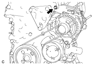
Tighten the bolt.
- Torque:
- 19 N*m{189 kgf*cm, 14 ft.*lbf}
 |
| 12. INSTALL V-RIBBED BELT |
Temporarily install the V-ribbed belt.
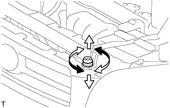
| 13. ADJUST V-RIBBED BELT |
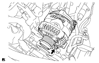
Turn bolt C to adjust the tension of the V-ribbed belt.
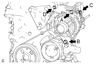 |
Tighten bolts A and B.
- Torque:
- for bolt A:
- 19 N*m{189 kgf*cm, 14 ft.*lbf}
- for bolt B:
- 43 N*m{438 kgf*cm, 32 ft.*lbf}
- NOTICE:
- Do not loosen bolt D.
| 14. INSPECT V-RIBBED BELT |
Check the belt for wear, cracks or other signs of damage.
If any of the following defects is found, replace the V-ribbed belt.- The belt is cracked.
- The belt is worn out to the extent that the cords are exposed.
- The belt has chunks missing from the ribs.
- The belt is cracked.
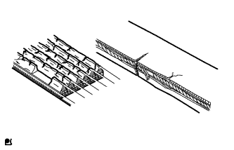 |
Check that the belt fits properly in the ribbed grooves.
- HINT:
- Check with your hand to confirm that the belt has not slipped out of the grooves on the bottom to the pulley. If it has slipped out, replace the V-ribbed belt. Install a new V-ribbed belt correctly.
 |
Check the V-ribbed belt deflection and tension.
- Standard Deflection:
Item Specified Condition New belt 7.0 to 8.2 mm (0.276 to 0.323 in.) Used belt 7.6 to 10.0 mm (0.299 to 0.394 in.)
- Standard Tension:
Item Specified Condition New belt 700 to 800 N (70 to 80 kgf, 157.4 to 179.8 lbf) Used belt 550 to 750 N (55 to 75 kgf, 123.6 to 168.6 lbf)
- HINT:
- When inspecting the V-ribbed belt deflection, apply 98 N (10 kgf, 22.0 lbf) of tensile force to it.
- Check the V-ribbed belt deflection at the specified point.
- V-ribbed belt tension and deflection should be checked after 2 revolutions of engine cranking.
- Measure the belt tension when the engine is cold.
- When adjusting the belt, be sure to adjust it so that the tension is as close as possible to the median of the specified range.
- When replacing the belt with a new one, be sure to perform the following after adjusting the belt: idle the engine for 5 minutes, and then adjust the belt to the specified value for a new belt after the engine has cooled.
- When inspecting a belt which has been used for over 5 minutes, apply the used belt specifications.
- When using a belt tension gauge, confirm its accuracy by using a master gauge first.
 |
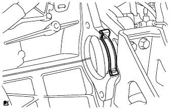
| 15. INSTALL REAR ENGINE UNDER COVER RH |
Install the under cover with the 3 clips.
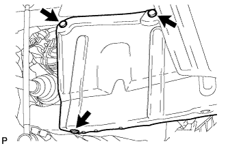 |
| 16. INSTALL FLYWHEEL HOUSING SIDE COVER |
Install the flywheel housing side cover to the cylinder block.
 |
| 17. INSTALL STARTER ASSEMBLY |
Install the starter with the 2 bolts.
- Torque:
- 37 N*m{380 kgf*cm, 27 ft.*lbf}
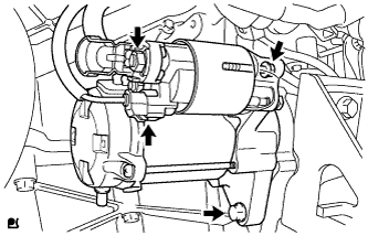 |
Connect the starter connector.
Connect starter wire with the nut.
- Torque:
- 9.8 N*m{100 kgf*cm, 87 in.*lbf}
Connect the terminal cap.
| 18. CONNECT CABLE TO NEGATIVE BATTERY TERMINAL |
| 19. ADD ENGINE COOLANT |
Tighten the radiator drain cock plug by hand.
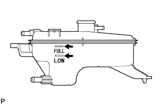
Add TOYOTA Super Long Life Coolant (SLLC) to the radiator reservoir filler opening until it is filled to the B line at the base of the reservoir filler neck.
- HINT:
- The B line is the lower edge of the inner wall of the filler neck.
- Standard capacity:
Item Specified Condition for Manual Transaxle 5.8 liters (6.1 US qts, 5.1 Imp. qts) for CVT 6.0 liters (6.3 US qts, 5.3 Imp. qts)
- HINT:
- TOYOTA vehicles are filled with TOYOTA SLLC at the factory. In order to avoid damage to the engine cooling system and other technical problems, only use TOYOTA SLLC or similar high quality ethylene glycol based non-silicate, non-amine, non-nitrite, non-borate coolant with long-life hybrid organic acid technology (coolant with long-life hybrid organic acid technology is a combination of low phosphates and organic acids).
- NOTICE:
- Never use water as a substitute for engine coolant.
 |
Press the No. 1 and No. 2 radiator hoses several times by hand, and then check the level of the coolant. If the coolant level drops below the B line, add TOYOTA SLLC to the B line.
Install the radiator reservoir cap.
Start the engine and warm it up until the cooling fan operates.
Set the air conditioning as follows while warming up the engine.
Measurement condition Item Condition Manual Air Conditioning System Fan speed: Any setting except off
Temperature: Toward WARM
Air conditioning switch: OffAutomatic Air Conditioning System Temperature: Toward MAX (HOT)
Air conditioning switch: OffMaintain the engine speed at 2000 to 2500 rpm and warm up the engine until the cooling fan operates.
- NOTICE:
- Make sure that the radiator reservoir still has some coolant in it.
- Pay attention to the needle of the coolant temperature meter. Make sure that the needle does not show an abnormally high temperature.
- If there is not enough coolant, the engine may burn out or overheat.
- After starting the engine, if the radiator reservoir does not have any coolant, perform the following: 1) stop the engine, 2) wait until the coolant has cooled down, and 3) add coolant until the coolant is filled to the B line.
- Run the engine at 2000 rpm until the coolant level has stabilized.
Press the No. 1 and No. 2 radiator hoses several times by hand to bleed air.
- CAUTION:
- When pressing the radiator hoses:
- Wear protective gloves.
- Be careful as the radiator hoses are hot.
- Keep your hands away from the radiator fan.
Stop the engine and wait until the coolant cools down to ambient temperature.
Check that the coolant level is between the FULL and LOW lines. If the coolant level is below the LOW line, repeat all of the procedures above.
If the coolant level is above the FULL line, drain coolant so that the coolant level is between the FULL and LOW lines.
 |
| 20. INSPECT FOR COOLANT LEAK |
Remove the radiator reservoir cap.
- CAUTION:
- To avoid the danger of being burned, do not remove the radiator reservoir cap while the engine and radiator are still hot. Thermal expansion will cause hot engine coolant and steam to blow out from the radiator reservoir.
Fill the radiator and reservoir with coolant, and then attach a radiator cap tester.
 |
Warm up the engine.
Pump the radiator cap tester to 118 kPa (1.2 kgf/cm2, 17.1 psi), and then check that the pressure does not drop.
If the pressure drops, check the hoses, radiator and water pump for leakage.
If there are no signs of external coolant leaks, check the heater core, cylinder block and head.
Reinstall the radiator reservoir cap.
| 21. INSPECT HOOD SUB-ASSEMBLY |
Check that the clearance measurements of areas A to J are within the standard range.

- Standard measurement:
Area Specified Condition Area Specified Condition A 7.1 +- 2.5 mm (0.278 +- 0.098 in.) F 0.6 +- 1.5 mm (0.024 +- 0.059 in.) B 3.6 +- 2.5 mm (0.140 +- 0.098 in.) G 3.5 +- 1.5 mm (0.138 +- 0.059 in.) C 5.9 +- 2.5 mm (0.230 +- 0.098 in.) H 0.5 +- 1.5 mm (0.020 +- 0.059 in.) D 0.2 +- 2.5 mm (0.006 +- 0.098 in.) I 3.5 +- 1.5 mm (0.138 +- 0.059 in.) E 3.5 +- 1.5 mm (0.138 +- 0.059 in.) J 0.0 +- 1.5 mm (0.000 +- 0.059 in.)
| 22. ADJUST HOOD SUB-ASSEMBLY |
Adjust the hood's position.
Loosen the hood's 4 hinge bolts.
Move the hood and adjust the clearance between the hood and front fender. Make sure that the clearance is within the standard range.
- Standard measurement:
Area Specified Condition E 3.5 +- 1.5 mm (0.138 +- 0.059 in.) G 3.5 +- 1.5 mm (0.138 +- 0.059 in.) I 3.5 +- 1.5 mm (0.138 +- 0.059 in.)
Tighten the hood's 4 hinge bolts after the adjustment.
- Torque:
- 13 N*m{133 kgf*cm, 10 ft.*lbf}

 |
Adjust the cushion rubber so that the height of the hood and fender are aligned.
Raise or lower the hood's front end by turning the cushion rubber. Make sure that the clearance is within the standard range.
- Standard measurement:
Area Specified Condition F 0.6 +- 1.5 mm (0.024 +- 0.059 in.) H 0.5 +- 1.5 mm (0.020 +- 0.059 in.) J 0.0 +- 1.5 mm (0.000 +- 0.059 in.)

 |
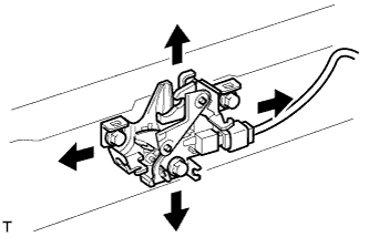
Adjust the hood lock.
Loosen the 3 bolts.
Adjust the hood lock position so that the striker can enter it smoothly.
Tighten the 3 bolts after the adjustment.
- Torque:
- 8.0 N*m{82 kgf*cm, 71 in.*lbf}
 |
| 23. INSTALL NO. 1 ENGINE UNDER COVER |
Install the under cover with the 6 screws and 10 clips.
 |
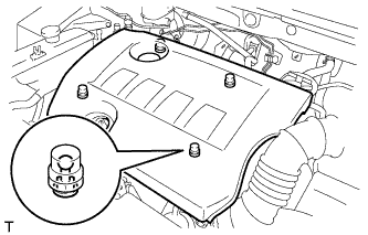
| 24. INSTALL NO. 2 CYLINDER HEAD COVER |
Attach the 4 clips to install the cover.
- NOTICE:
- Be sure to attach the clips securely.
- Do not apply excessive force or do not hit the cover to attach the clips. This may cause the cover to break.
 |
| 25. INSTALL RADIATOR SUPPORT OPENING COVER |
Install the radiator support opening cover with the 9 clips.