Oil Pump -- Removal |
| 1. REMOVE ENGINE ASSEMBLY WITH TRANSAXLE |
Remove the engine assembly with transaxle (RAV4_ACA30 RM000003PXM007X.html).
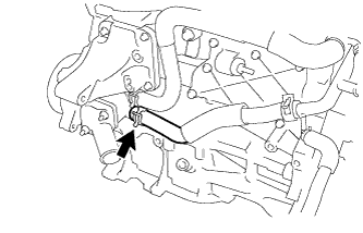
| 2. REMOVE ENGINE OIL LEVEL DIPSTICK GUIDE |
Remove the engine oil level dipstick.
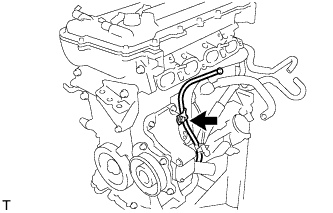 |
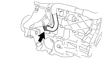
Remove the bolt and dipstick guide.
Remove the O-ring from the dipstick guide.
| 3. DISCONNECT NO. 3 WATER BY-PASS HOSE |
Disconnect the No. 3 water by-pass hose from the water inlet housing.
 |
| 4. DISCONNECT WATER INLET HOSE |
Disconnect the water inlet hose from the water inlet housing.
 |
| 5. REMOVE WATER INLET |
Remove the 2 nuts and disconnect the water inlet.
 |
| 6. REMOVE THERMOSTAT |
Remove the thermostat.
 |
Remove the gasket from the thermostat.
| 7. REMOVE IGNITION COIL ASSEMBLY |
Disconnect the 4 ignition coil connectors.
 |
Remove the 4 bolts and 4 ignition coils.
- NOTICE:
- When removing the ignition coil, do not damage the plug cap with the cylinder head cover opening or the upper edge of the spark plug tube.
Text in Illustration *1 Cylinder Head Cover *2 Spark Plug Tube *3 Plug Cap
 |
| 8. REMOVE RADIO SETTING CONDENSER |
Remove the bolt and setting condenser.
 |
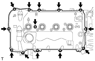
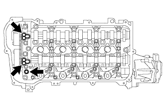
| 9. REMOVE CYLINDER HEAD COVER SUB-ASSEMBLY |
Remove the 13 bolts, seal washer and cylinder head cover.
 |
Remove the 3 gaskets from the camshaft bearing cap.
- NOTICE:
- As gaskets may stick to the cylinder head cover, be careful not to drop any of the gaskets into the engine when removing the cylinder head cover.
 |
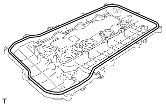
| 10. REMOVE CYLINDER HEAD COVER GASKET |
Remove the cylinder head cover gasket.
 |
| 11. REMOVE SPARK PLUG TUBE GASKET |
Pry up the 4 claws of the ventilation baffle plate.
- NOTICE:
- Do not deform the claws of the baffle plate more than necessary.
 |
Remove the 4 gaskets from the cylinder head cover.
- HINT:
- Prevent the plug tube gaskets from being deformed as much as possible. The removed gaskets will be used when installing new gaskets.
- NOTICE:
- Be careful not to damage the cylinder head cover.
| 12. SET NO. 1 CYLINDER TO TDC/COMPRESSION |
Turn the crankshaft pulley until its notch and timing mark "0" of the timing chain cover are aligned.
Text in Illustration *1 Timing Mark *2 Timing Notch
 |
Check that timing marks on both the camshaft timing exhaust gear and camshaft timing gear are facing upward as shown in the illustration.
- HINT:
- If not, turn the crankshaft 1 complete revolution (360°) and align the marks as above.
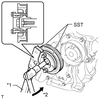
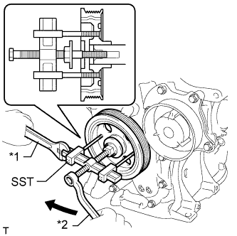
| 13. REMOVE CRANKSHAFT PULLEY |
Using SST, hold the crankshaft pulley and loosen the pulley bolt. Further loosen the bolt until 2 or 3 threads are screwed into the crankshaft.
Text in Illustration *1 Hold *2 Turn - SST
- 09213-58014(91551-80840)
09330-00021
 |
Using SST and the pulley bolt, remove the crankshaft pulley and pulley bolt.
Text in Illustration *1 Hold *2 Turn - SST
- 09950-50013(09951-05010,09952-05010,09953-05020,09954-05021)
- HINT:
- Apply lubricant to the threads and end of SST.
 |
| 14. REMOVE NO. 1 CHAIN TENSIONER ASSEMBLY |
Remove the 2 nuts, bracket, chain tensioner and gasket.
- NOTICE:
- Do not turn the crankshaft without the No. 1 chain tensioner installed.
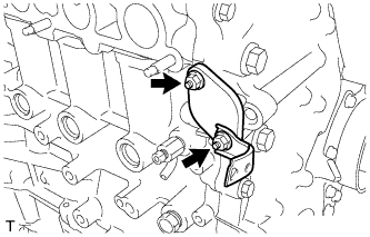 |
| 15. REMOVE TIMING CHAIN COVER SUB-ASSEMBLY |
Remove the 3 bolts and engine mounting bracket.
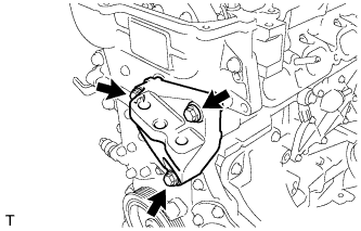 |
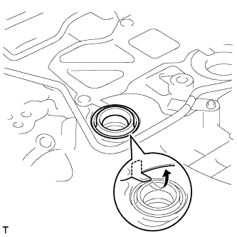
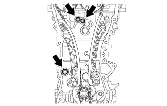
Remove the 4 bolts and oil filter bracket.
 |
Remove the 2 O-rings.
 |
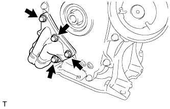
Remove the 19 bolts.
 |
Remove the timing chain cover by prying between the timing chain cover and cylinder head, camshaft housing, cylinder block and stiffening crankcase with a screwdriver as shown in the illustration.
Text in Illustration *1 Protective Tape - HINT:
- Tape the screwdriver tip before use.
- NOTICE:
- Be careful not to damage the contact surfaces of the cylinder head, camshaft housing, cylinder block, stiffening crankcase and timing chain cover.
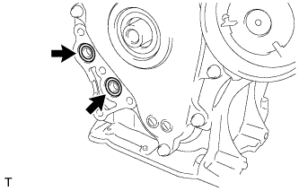
 |
Remove the 3 O-rings.
 |
Remove the 3 bolts and water pump.
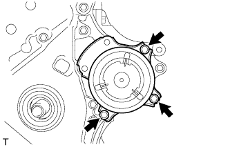 |
Remove the gasket.
 |
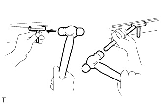
| 16. REMOVE TIMING CHAIN COVER OIL SEAL |
Place the timing chain cover on wooden blocks.
Text in Illustration *1 Wooden Block *2 Protective Tape
 |
Using a screwdriver, tap out the oil seal.
- HINT:
- Tape the screwdriver tip before use.
- NOTICE:
- Do not damage the surface of the oil seal press fit hole.
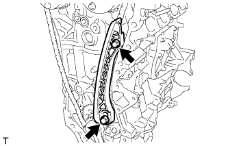
| 17. REMOVE CHAIN TENSIONER SLIPPER |
Remove the chain tensioner slipper from the cylinder block.
 |
| 18. REMOVE NO. 1 CHAIN VIBRATION DAMPER |
Remove the 2 bolts and chain vibration damper.
 |
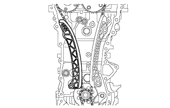
| 19. REMOVE CHAIN SUB-ASSEMBLY |
Hold the hexagonal portion of the camshaft with a wrench and turn the camshaft timing gear counterclockwise to loosen the chain between the camshaft timing gears.
 |
With the chain loosened, release the chain from the camshaft timing gear and place it on the camshaft timing gear.
- HINT:
- Be sure to release the chain from the sprocket completely.
Turn the camshaft clockwise to return it to the original position and remove the chain.
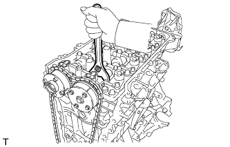
| 20. REMOVE CRANKSHAFT TIMING SPROCKET |
Remove the crankshaft timing sprocket.
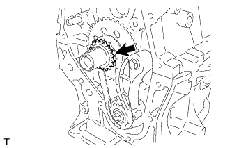 |
| 21. REMOVE NO. 2 CHAIN SUB-ASSEMBLY |
Temporarily install the crankshaft pulley with the pulley bolt.
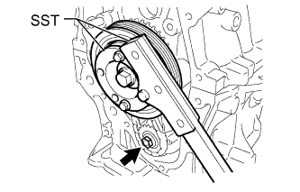 |
Using SST, hold the crankshaft. Then remove the drive shaft gear nut.
- SST
- 09213-58014(91551-80840)
09330-00021
Remove SST, the crankshaft pulley bolt and crankshaft pulley.
Remove the bolt, chain tensioner plate and spring.
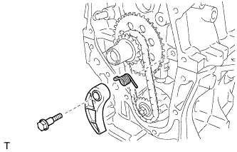 |
Remove the oil pump drive gear, oil pump drive shaft gear and No. 2 chain.
Text in Illustration *1 Oil Pump Dive Gear *2 Oil Pump Drive Shaft Gear *3 No. 2 Chain Sub-Assembly
 |
| 22. REMOVE NO. 2 OIL PAN SUB-ASSEMBLY |
Remove the 10 bolts and 2 nuts.
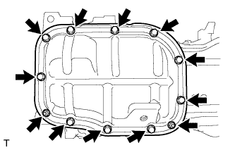 |
Insert the blade of an oil pan seal cutter between the crankcase and oil pan. Cut through the sealer and remove the oil pan.
- NOTICE:
- Be careful not to damage the surface of the oil pan which contacts the stiffening crankcase.
- Be careful not to damage the stiffening crankcase flange.
 |
| 23. REMOVE OIL PUMP ASSEMBLY |
Remove the 3 bolts and oil pump.
 |