Navigation System (For Dvd) Speed Signal Circuit
Navigation. Toyota Rav4. Aca30, 33, 38 Gsa33 Zsa30, 35
DESCRIPTION
WIRING DIAGRAM
INSPECTION PROCEDURE
CHECK VEHICLE SPEED SIGNAL (DISPLAY CHECK MODE)
CHECK HARNESS AND CONNECTOR (NAVIGATION RECEIVER - COMBINATION METER)
NAVIGATION SYSTEM (for DVD) - Speed Signal Circuit |
DESCRIPTION
Navigation function:The navigation receiver assembly receives a vehicle speed signal from the combination meter assembly and information about the navigation antenna, and then adjusts vehicle position.ASL function:The circuit is necessary for the ASL (Automatic Sound Levelizer) built into the navigation receiver. Speed signals are received from the combination meter and used for the ASL. The ASL function automatically adjusts the sound volume in order to maintain clear audio sound even when vehicle noise increases (as vehicle noise increases, the volume is turned up, etc.).- HINT:
- A voltage of 12 V or 5 V is output from each ECU and then input to the combination meter assembly. The signal is changed to a pulse signal at the transistor in the combination meter assembly. Each ECU controls the respective systems based on the pulse signal.
- If a short occurs in any of the ECUs or in the wire harness connected to an ECU, all systems in the diagram below will not operate normally.
WIRING DIAGRAM
INSPECTION PROCEDURE
| 1.CHECK VEHICLE SPEED SIGNAL (DISPLAY CHECK MODE) |
Enter the "Display Check" mode and select "Vehicle Signal Check" (RAV4_ACA30 RM000003A3N00LX.html).
Check that the vehicle speed on the display changes according to the actual vehicle speed.
- OK:
- The display changes according to the actual vehicle speed.
- HINT:
- This display is updated once per second. As a result, it is normal for the display to lag behind the actual change in the vehicle speed.
| 2.CHECK HARNESS AND CONNECTOR (NAVIGATION RECEIVER - COMBINATION METER) |
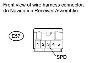
Disconnect the E57 navigation receiver assembly connector.
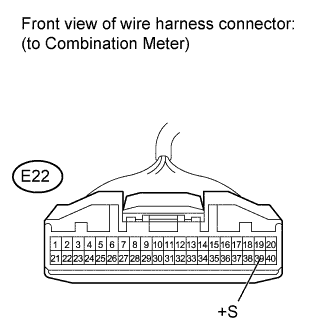
Disconnect the E22 combination meter connector.
Measure the resistance according to the value(s) in the table below.
- Standard Resistance:
Tester Connection
| Condition
| Specified Condition
|
E57-3 (SPD) - E22-39 (+S)
| Always
| Below 1 Ω
|
| | REPAIR OR REPLACE HARNESS OR CONNECTOR |
|
|