Front Wheel Alignment -- Adjustment |
- NOTICE:
- For vehicles equipped with VSC, if the wheel alignment has been adjusted, and if suspension or underbody components have been removed/installed or replaced, be sure to perform the following initialization procedure in order for the system to function normally:
- Disconnect the negative battery cable for more than 2 seconds.
- Reconnect the negative battery terminal.
- Perform zero point calibration of the yaw rate and acceleration sensor and test mode inspection (RAV4_ACA30 RM000001K1O00SX.html).
| 1. INSPECT TIRES |
Inspect the tires (RAV4_ACA30 RM000001Y9S003X.html).
| 2. MEASURE VEHICLE HEIGHT |
 |
- NOTICE:
- Before inspecting the wheel alignment, adjust the vehicle height to the specification.
Press down on the vehicle several times to stabilize the suspension, and measure the vehicle height.
Measure the front vehicle height.
Measure the distance from the ground to the center of the lower suspension arm front mounting bolt.
Measure the rear vehicle height.
Measure the distance from the ground to the center of the body side No. 2 suspension arm mounting bolt.
- Standard vehicle height (unloaded vehicle):
Item Front C - A Rear D - B 215/70R16*1 89 mm (3.50 in.) 59 mm (2.32 in.) 225/65R17
235/55R1897 mm (3.82 in.) 67 mm (2.64 in.)*1
65 mm (2.56 in.)*2Australia 87 mm (3.43 in.) 55 mm (2.17 in.)
- *1: Europe only
- *2: Other
- NOTICE:
- The standard value shown here is a value that is used for adjusting the wheel alignment and does not indicate the height of an actual vehicle.
- HINT:
- If the vehicle height is not as specified, press down on the vehicle several times to stabilize the suspension. Then measure the vehicle height again.
| 3. INSPECT CAMBER, CASTER AND STEERING AXIS INCLINATION |
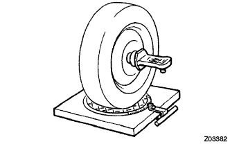 |
Install the camber-caster-kingpin gauge or place the front wheels on the center of the wheel alignment tester.
Inspect the camber, caster and steering axis inclination.
- Standard camber inclination (unloaded vehicle):
Item Camber Inclination *215/70R16 -0°08' +/-45' (-0.13° +/-0.75°) 225/65R17
235/55R18-0°11' +/-45' (-0.18° +/-0.75°) Australia -0°07' +/-45' (-0.12° +/-0.75°)
- Standard caster inclination (unloaded vehicle):
Item Caster Inclination 215/70R16 *1 5°46' +/-45' (5.77° +/-0.75°) 225/65R17
235/55R185°51' +/-45' (5.85° +/-0.75°) *1
5°50' +/-45' (5.83° +/-0.75°) *2Australia 5°42' +/-45' (5.70° +/-0.75°)
- *1: Europe only
- *2: Other
- Standard steering axis inclination (unloaded vehicle):
Item Steering Axis Inclination *215/70R16 11°16' +/-45' (11.27° +/-0.75°) 225/65R17
235/55R1811°26' +/-45' (11.44° +/-0.75°) Australia 11°14' +/-45' (11.23° +/-0.75°)
| 4. ADJUST CAMBER AND CASTER |
- NOTICE:
- After the camber has been adjusted, inspect the toe-in.
Remove the front wheel.
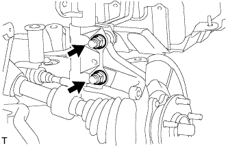
Remove the 2 nuts on the lower side of the shock absorber.
- NOTICE:
- When removing the nut, stop the bolt from rotating and loosen the nut.
 |
Clean the installation surfaces of the shock absorber and the steering knuckle.
Temporarily install the 2 nuts.
Fully push or pull the front axle hub in the direction of the required adjustment.
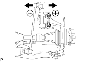 |
Tighten the 2 nuts.
- Torque:
- 240 N*m{2,447 kgf*cm, 177 ft.*lbf}
- NOTICE:
- Keep the bolts from rotating and torque the nuts.
Install the front wheel.
- Torque:
- 103 N*m{1,050 kgf*cm, 76 ft.*lbf}
Check the camber.
- If the measured value is not within the specified range, calculate the required adjustment amount using the formula below.

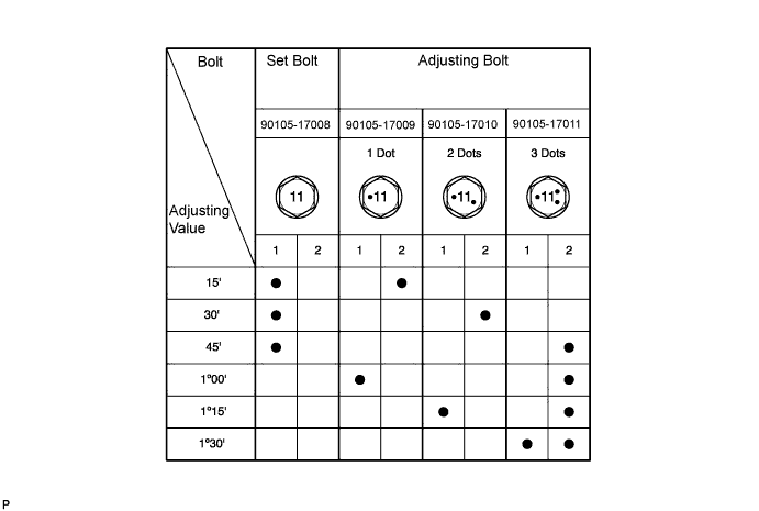
- If the camber is not within the specification, estimate how much additional camber adjustment will be required and select the camber adjusting bolt using the following table.
- If the measured value is not within the specified range, calculate the required adjustment amount using the formula below.
Repeat the steps mentioned above. When temporarily installing the 2 nuts, replace 1 or 2 selected bolts.
- HINT:
- Replace 1 bolt at a time when replacing 2 bolts.
| 5. INSPECT TOE-IN |
 |
- Standard toe-in (unloaded vehicle):
Tire Size Front A + B
Rear C - D*215/70R16
225/65R17
235/55R18A + B: 0°05' +/-10' (0.08° +/-0.16°)
C - D: 1.0 +/-2.0 mm (0.04 +/-0.08 in.)
- HINT:
- If the toe-in is not as specified, adjust it at the rack ends.
| 6. ADJUST TOE-IN |
 |
Remove the boot clips.
Loosen the tie rod end lock nuts.
Turn the right and left rack ends by an equal amount to adjust the toe-in to the center value.
Make sure that the length of the right and left rack ends are approximately the same.
- Standard difference:
- 1.5 mm (0.0590 in.) or less
 |
Tighten the tie rod end lock nuts.
- Torque:
- 88 N*m{897 kgf*cm, 65 ft.*lbf}
Place the boots on the seats and install the clips.
- HINT:
- Make sure that the boots are not twisted.
| 7. INSPECT WHEEL ANGLE |
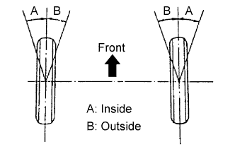 |
Turn the steering wheel to the left and right full lock positions, and measure the turning angle.
- Standard wheel angle (unloaded vehicle):
Item Inside Wheel Angle Outside Wheel Angle (Reference) *215/70R16 38°55' (36°55' to 40°55')
(38.9° {36.9° to 40.9°})32°20'
(32.3°)225/65R17 38°44' (36°44' to 40°44')
(38.7° {36.7° to 40.7°})32°13'
(30.2°)235/55R18 35°50' (33°55' to 37°55')
(35.8° {33.8° to 37.9°})30°29'
(30.5°)Australia 38°58' (36°58' to 40°58')
(39.0° {37.0° to 41.0°})32°22'
(32.4°)
- HINT:
- If the angles are not as specified, check and adjust the right and left rack end lengths.
| 8. DISCONNECT CABLE FROM NEGATIVE BATTERY TERMINAL |
- NOTICE:
- Disconnect the negative battery cable for more than 2 seconds.
| 9. CONNECT CABLE TO NEGATIVE BATTERY TERMINAL |
- Torque:
- 5.4 N*m{55 kgf*cm, 48 in.*lbf}
| 10. PERFORM YAW RATE AND DECELERATION SENSOR ZERO POINT CALIBRATION |
Perform the yaw rate and deceleration sensor zero point calibration (RAV4_ACA30 RM000001K1O00SX.html).