Front Drive Shaft Assembly (For 2Wd) Removal
Drive Line. Toyota Rav4. Aca30, 33, 38 Gsa33 Zsa30, 35
Drive Shaft. Toyota Rav4. Aca30, 33, 38 Gsa33 Zsa30, 35
REMOVE FRONT WHEEL
DRAIN AUTOMATIC TRANSAXLE FLUID
DRAIN TRANSAXLE OIL
REMOVE FRONT AXLE HUB NUT
REMOVE FRONT SPEED SENSOR LH
REMOVE FRONT SPEED SENSOR RH
DISCONNECT FRONT DISC BRAKE CYLINDER ASSEMBLY LH
DISCONNECT FRONT DISC BRAKE CYLINDER ASSEMBLY RH
REMOVE FRONT STABILIZER LINK ASSEMBLY LH
REMOVE FRONT STABILIZER LINK ASSEMBLY RH
DISCONNECT FRONT SUSPENSION LOWER NO. 1 ARM SUB-ASSEMBLY LH
DISCONNECT FRONT SUSPENSION LOWER NO. 1 ARM SUB-ASSEMBLY RH
DISCONNECT STEERING KNUCKLE WITH AXLE HUB LH
DISCONNECT STEERING KNUCKLE WITH AXLE HUB RH
DISCONNECT TIE ROD END SUB-ASSEMBLY LH
DISCONNECT TIE ROD END SUB-ASSEMBLY RH
REMOVE FRONT DRIVE SHAFT ASSEMBLY LH
REMOVE FRONT DRIVE SHAFT ASSEMBLY RH
Front Drive Shaft Assembly (For 2Wd) -- Removal |
| 2. DRAIN AUTOMATIC TRANSAXLE FLUID |
Remove the drain plug and gasket, and drain ATF.
Install a new gasket and the drain plug.
- Torque:
- 47 N*m{479 kgf*cm, 35 ft.*lbf}
for E352:
Drain the transaxle oil (RAV4_ACA30 RM000001YVO00BX_01_0015.html).
for EB61:
Drain the transaxle oil (RAV4_ACA30 RM000002Z2L015X_01_0001.html).
| 4. REMOVE FRONT AXLE HUB NUT |
Using SST and a hammer, unstake the staked part of the nut.
- SST
- 09930-00010
- NOTICE:
- Loosen the staked part of the nut completely, otherwise the screw of the drive shaft may be damaged.
While applying the brakes, remove the lock axle hub nut.
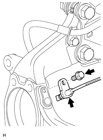
| 5. REMOVE FRONT SPEED SENSOR LH |
Disconnect the sensor connector.
Remove the sensor clip (labeled A), bolt (labeled B) and sensor clamp (labeled C).
Remove the sensor clip (labeled D), bolt (labeled E) and sensor clamp (labeled F).
Remove the bolt and sensor from the knuckle.
- NOTICE:
- Keep the sensor tip and sensor installation hole free from foreign matter.
| 6. REMOVE FRONT SPEED SENSOR RH |
- HINT:
- Use the same procedures described for the LH side.
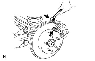
| 7. DISCONNECT FRONT DISC BRAKE CYLINDER ASSEMBLY LH |
Remove the 2 bolts and cylinder.
| 8. DISCONNECT FRONT DISC BRAKE CYLINDER ASSEMBLY RH |
- HINT:
- Use the same procedures described for the LH side.
| 9. REMOVE FRONT STABILIZER LINK ASSEMBLY LH |
Remove the 2 nuts and stabilizer link.
| 10. REMOVE FRONT STABILIZER LINK ASSEMBLY RH |
- HINT:
- Use the same procedures described for the LH side.
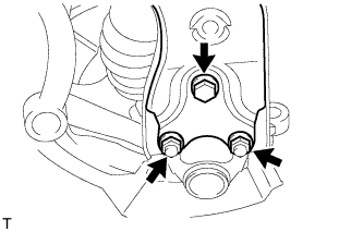
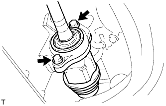
| 11. DISCONNECT FRONT SUSPENSION LOWER NO. 1 ARM SUB-ASSEMBLY LH |
Remove the bolt and 2 nuts.
Disconnect the lower arm from the ball joint.
| 12. DISCONNECT FRONT SUSPENSION LOWER NO. 1 ARM SUB-ASSEMBLY RH |
- HINT:
- Use the same procedures described for the LH side.
| 13. DISCONNECT STEERING KNUCKLE WITH AXLE HUB LH |
Put matchmarks on the drive shaft and axle hub.
- NOTICE:
- Do not punch the marks.
Using a plastic-faced hammer, disconnect the steering knuckle with axle hub.
- NOTICE:
- Be careful not to damage the boot and speed sensor rotor.
- Do not excessively push out the drive shaft from the axle assembly.
| 14. DISCONNECT STEERING KNUCKLE WITH AXLE HUB RH |
- HINT:
- Use the same procedures described for the LH side.
| 15. DISCONNECT TIE ROD END SUB-ASSEMBLY LH |
Remove the cotter pin and castle nut.
Using SST, disconnect the tie rod end from the steering knuckle.
- SST
- 09628-62011
- NOTICE:
- Do not damage the tie rod end dust cover.
| 16. DISCONNECT TIE ROD END SUB-ASSEMBLY RH |
- HINT:
- Use the same procedures described for the LH side.
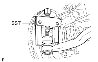
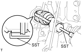
| 17. REMOVE FRONT DRIVE SHAFT ASSEMBLY LH |
Using SST, remove the front drive shaft.
- SST
- 09520-01010
09520-24010(09520-32040)
- NOTICE:
- Be careful not to damage the transaxle case oil seal, inboard joint boot and drive shaft dust cover.
- Be careful not to drop the drive shaft.
| 18. REMOVE FRONT DRIVE SHAFT ASSEMBLY RH |
Remove the 2 bolts and pull out the drive shaft together with the drive shaft bearing case.
Remove the drive shaft from the transaxle.
- NOTICE:
- Be careful not to damage the transaxle case oil seal, inboard joint boot and drive shaft dust cover.
- Be careful not to drop the drive shaft.