Differential Oil Seal Replacement
DRAIN TRANSAXLE OIL
REMOVE FRONT WHEEL
REMOVE NO. 1 ENGINE UNDER COVER
REMOVE FRONT EXHAUST PIPE
REMOVE FRONT SPEED SENSOR LH
REMOVE FRONT SPEED SENSOR RH
DISCONNECT FRONT STABILIZER LINK ASSEMBLY LH
DISCONNECT FRONT STABILIZER LINK ASSEMBLY RH
DISCONNECT FRONT SUSPENSION NO. 1 LOWER ARM SUB-ASSEMBLY LH
DISCONNECT FRONT SUSPENSION NO. 1 LOWER ARM SUB-ASSEMBLY RH
REMOVE FRONT DRIVE SHAFT ASSEMBLY LH
REMOVE FRONT DRIVE SHAFT ASSEMBLY RH
REMOVE TRANSAXLE CASE OIL SEAL LH
REMOVE TRANSAXLE CASE OIL SEAL RH
INSTALL TRANSAXLE CASE OIL SEAL LH
INSTALL TRANSAXLE CASE OIL SEAL RH
INSTALL FRONT DRIVE SHAFT ASSEMBLY LH
INSTALL FRONT DRIVE SHAFT ASSEMBLY RH
CONNECT FRONT SUSPENSION NO. 1 LOWER ARM SUB-ASSEMBLY LH
CONNECT FRONT SUSPENSION NO. 1 LOWER ARM SUB-ASSEMBLY RH
CONNECT FRONT STABILIZER LINK ASSEMBLY LH
INSTALL FRONT STABILIZER LINK ASSEMBLY RH
INSTALL FRONT SPEED SENSOR LH
INSTALL FRONT SPEED SENSOR RH
INSTALL FRONT EXHAUST PIPE
INSTALL NO. 1 ENGINE UNDER COVER
INSTALL FRONT WHEEL
ADD TRANSAXLE OIL
INSPECT MANUAL TRANSAXLE OIL
INSPECT FRONT WHEEL ALIGNMENT
Differential Oil Seal -- Replacement |
- HINT:
- Use the same procedure for the RH side (transaxle case oil seal) and LH side (transaxle case oil seal).
- The procedure listed below are for the LH side (transaxle case oil seal).
Remove the filler plug and gasket.
Remove the drain plug and gasket, and then drain the manual transaxle oil.
Install a new gasket and the drain plug.
- Torque:
- 49 N*m{500 kgf*cm, 36 ft.*lbf}
| 3. REMOVE NO. 1 ENGINE UNDER COVER |
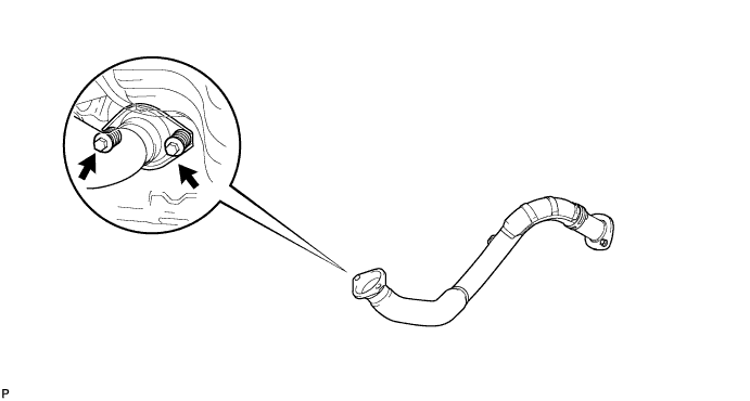
| 4. REMOVE FRONT EXHAUST PIPE |
Remove the 2 bolts, 2 compression springs and front exhaust pipe.
Remove the gasket from the exhaust manifold.
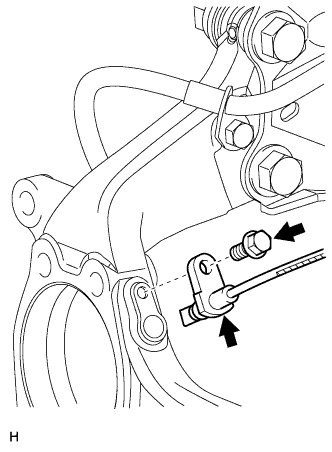
| 5. REMOVE FRONT SPEED SENSOR LH |
Disconnect the sensor connector.
Remove the sensor clip (labeled A), bolt (labeled B) and sensor clamp (labeled C).
Remove the sensor clip (labeled D), bolt (labeled E) and sensor clamp (labeled F).
Remove the bolt and sensor from the knuckle.
- NOTICE:
- Keep the sensor tip and sensor installation hole free from foreign matter.
| 6. REMOVE FRONT SPEED SENSOR RH |
- HINT:
- Use the same procedures described for the LH side.
| 7. DISCONNECT FRONT STABILIZER LINK ASSEMBLY LH |
Remove the 2 nuts and stabilizer link.
| 8. DISCONNECT FRONT STABILIZER LINK ASSEMBLY RH |
- HINT:
- Use the same procedures described for the LH side.
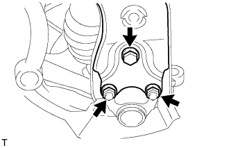
| 9. DISCONNECT FRONT SUSPENSION NO. 1 LOWER ARM SUB-ASSEMBLY LH |
Remove the bolt and 2 nuts.
Disconnect the lower arm from the ball joint.
| 10. DISCONNECT FRONT SUSPENSION NO. 1 LOWER ARM SUB-ASSEMBLY RH |
- HINT:
- Use the same procedures described for the LH side.
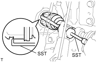
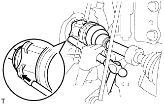
| 11. REMOVE FRONT DRIVE SHAFT ASSEMBLY LH |
Using SST, remove the front drive shaft.
- SST
- 09520-01010
09520-24010(09520-32040)
- NOTICE:
- Be careful not to damage the transaxle case oil seal, inboard joint boot and drive shaft dust cover.
- Be careful not to drop the drive shaft.
| 12. REMOVE FRONT DRIVE SHAFT ASSEMBLY RH |
- HINT:
- Use the same procedures described for the LH side.
| 13. REMOVE TRANSAXLE CASE OIL SEAL LH |
Using SST, tap out the transaxle case oil seal.
- SST
- 09308-00010
| 14. REMOVE TRANSAXLE CASE OIL SEAL RH |
- SST
- 09308-00010
Using SST, tap out the transaxle case oil seal.
| 15. INSTALL TRANSAXLE CASE OIL SEAL LH |
Coat the lip of a new oil seal with MP grease.
Using SST and a hammer, tap in the oil seal.
- SST
- 09608-10010
09950-70010(09951-07200)
- Standard depth:
- 3.0 to 4.0 mm (0.118 to 0.158 in.)
- NOTICE:
- Be careful not to damage the lip of the oil seal.
| 16. INSTALL TRANSAXLE CASE OIL SEAL RH |
Coat the lip of a new transaxle case oil seal with MP grease.
Using SST and a hammer, tap in the oil seal.
- SST
- 09608-10010
09950-70010(09951-07200)
- Standard depth:
- 5.5 to 6.5 mm (0.22 to 0.26 in.)
- NOTICE:
- Be careful not to damage the lip of the oil seal.
| 17. INSTALL FRONT DRIVE SHAFT ASSEMBLY LH |
Coat the splines of the inboard joint shaft with gear oil.
Align the shaft splines and tap in the drive shaft with a brass bar and hammer.
- NOTICE:
- Set the snap ring with the opening facing downwards.
- Be careful not to damage the oil seal, boot and dust cover.
| 18. INSTALL FRONT DRIVE SHAFT ASSEMBLY RH |
- HINT:
- Use the same procedures described for the LH side.
| 19. CONNECT FRONT SUSPENSION NO. 1 LOWER ARM SUB-ASSEMBLY LH |
Connect the lower arm to the ball joint with the 2 bolts and nut.
- Torque:
- 92 N*m{938 kgf*cm, 68 ft.*lbf}
| 20. CONNECT FRONT SUSPENSION NO. 1 LOWER ARM SUB-ASSEMBLY RH |
- HINT:
- Use the same procedures described for the LH side.
| 21. CONNECT FRONT STABILIZER LINK ASSEMBLY LH |
Install the link with the 2 nuts.
- Torque:
- 74 N*m{755 kgf*cm, 55 ft.*lbf}
| 22. INSTALL FRONT STABILIZER LINK ASSEMBLY RH |
- HINT:
- Use the same procedures described for the LH side.
| 23. INSTALL FRONT SPEED SENSOR LH |
- NOTICE:
- To prevent interference with other parts, do not twist the painted line areas of the sensor wire when installing it.
Set the sensor into the knuckle, and then install the sensor with the bolt.
- Torque:
- 8.5 N*m{87 kgf*cm, 75 in.*lbf}
- NOTICE:
- Keep the sensor tip and sensor installation hole free from foreign matter.
- Firmly insert the sensor body into the knuckle before tightening the bolt.
- After installing the sensor to the knuckle, make sure that there is no clearance between the sensor stay and knuckle. Also make sure that no foreign matter is stuck between the parts.
- To prevent interference between the sensor and magnetic rotor, do not rotate the sensor body during or after the insertion of the sensor body to the knuckle.
Install the sensor clamp and sensor clip as follows.
Simultaneously perform the following: 1) hang the hook part of the sensor clamp (labeled A) on the part of the flexible hose bracket (labeled C); and 2) insert the hook part of the sensor clamp (labeled B) to the part of the flexible hose bracket (labeled D).
- NOTICE:
- Do not twist the sensor wire when installing the clamp.
Install the sensor clamp to the flexible hose clamp and flexible hose bracket with the bolt (labeled E).
- Torque:
- 18.5 N*m{189 kgf*cm, 14 ft.*lbf}
Insert the sensor clip (labeled F) into the hole on the absorber lower bracket.
Install the sensor clamp and sensor clip as follows.
Set the sensor clamp (labeled G) on the side member, and then install the bolt (labeled H).
- Torque:
- 8.5 N*m{87 kgf*cm, 75 in.*lbf}
- NOTICE:
- Do not twist the sensor wire when installing the clamp.
Insert the sensor clip (labeled I) into the hole on the apron.
Connect the sensor connector.
| 24. INSTALL FRONT SPEED SENSOR RH |
- HINT:
- Use the same procedures described for the LH side.
| 25. INSTALL FRONT EXHAUST PIPE |
Using a vernier caliper, measure the free length of the compression spring.
- Minimum length:
- 41.5 mm (1.634 in.)
If the length is less than the minimum, replace the compression spring.
Install a new gasket by hand so that its surface is flush with the exhaust manifold.
- NOTICE:
- Make sure the gasket is facing the correct direction.
- Do not reuse the removed gasket.
- Do not push in the gasket while installing the front exhaust pipe.
Install the front exhaust pipe with the 2 compression springs and 2 bolts.
- Torque:
- 43 N*m{438 kgf*cm, 32 ft.*lbf}
| 26. INSTALL NO. 1 ENGINE UNDER COVER |
- Torque:
- 103 N*m{1,050 kgf*cm, 76 ft.*lbf}
| 29. INSPECT MANUAL TRANSAXLE OIL |
Inspect manual transaxle (RAV4_ACA30 RM000001YV2006X.html).
| 30. INSPECT FRONT WHEEL ALIGNMENT |