Transmission Control Cable Installation
INSTALL TRANSAXLE CONTROL CABLE ASSEMBLY
CONNECT TRANSAXLE CONTROL CABLE ASSEMBLY
ADJUST TRANSMISSION CONTROL CABLE ASSEMBLY
INSTALL REAR CONSOLE BOX SUB-ASSEMBLY
INSTALL CONSOLE REAR END PANEL
INSTALL UPPER REAR CONSOLE PANEL SUB-ASSEMBLY
INSTALL CONSOLE CUP HOLDER BOX
INSTALL SWITCH BASE
INSTALL UPPER CONSOLE PANEL SUB-ASSEMBLY
INSTALL SHIFT LEVER KNOB SUB-ASSEMBLY
INSTALL NO. 2 CONSOLE UPPER PANEL GARNISH
INSTALL NO. 1 CONSOLE UPPER PANEL GARNISH
INSTALL AIR CLEANER CASE
INSTALL AIR CLEANER CAP SUB-ASSEMBLY
INSTALL NO. 2 CYLINDER HEAD COVER
Transmission Control Cable -- Installation |
| 1. INSTALL TRANSAXLE CONTROL CABLE ASSEMBLY |
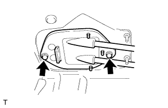
Install the retainer with the 2 bolts.
- Torque:
- 5.0 N*m{51 kgf*cm, 44 in.*lbf}
Connect the 2 cables to the control cable bracket with 2 new clips.
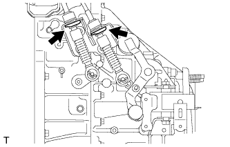
Connect the 2 cables to the transaxle and install the 2 clips.
| 2. CONNECT TRANSAXLE CONTROL CABLE ASSEMBLY |
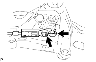
Connect the ends of the control cable and install the 2 clips to the shift lever.
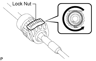
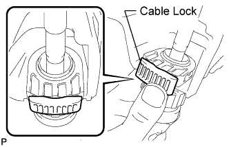
Turn the lock nuts of the shift cable 270° counterclockwise, and hold them in that position.
Install the shift cable while holding them.
Check that the cables are installed securely.
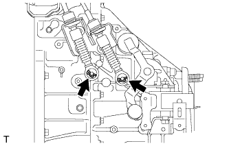
Push in the cable locks of the shift cable and select cable.
Connect the cable ends of the control cable and install the 2 clips.
| 3. ADJUST TRANSMISSION CONTROL CABLE ASSEMBLY |
- HINT:
- After the shift lever or the shift cable is replaced, be sure to adjust the transmission control cable assembly.
- If the shift lever does not move (or the shift lever is difficult to move) to the 1st or 2nd position, or if it is possible to move the shift lever to reverse without pulling up the slider shaft, the length of the cable must be adjusted.
To release the lock (lock condition to lock release condition).
- HINT:
- While holding the shift lever in the reverse direction, lock the cable length adjustment mechanism of the select cable.
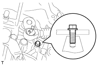
Align the hole of the select outer lever with the hole in the transmission.
Insert a bolt into the aligned holes to fix the select outer lever in place.
- NOTICE:
- Do not push in the bolt forcefully (avoid case damage).
- HINT:
- Use a bolt with a diameter of 6 mm (0.236 in.) and a length of at least 16 mm (0.630 in.).
- Depending on the actual bolt diameter, it may be difficult to insert the bolt. In that case, as there is some variation in actual bolt diameters, use a 6.0 mm (0.236 in.) bolt with a comparatively small diameter.
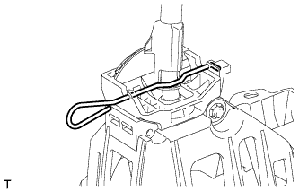
Turn the shift lever in the reverse direction without pulling up the slider shaft.
While holding the shift lever in the reverse direction, lock the cable length adjustment mechanism of the select cable.
Remove the bolt to free the select outer lever.
for new shift lever:
Remove the stopper pin and dispose of it.
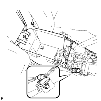
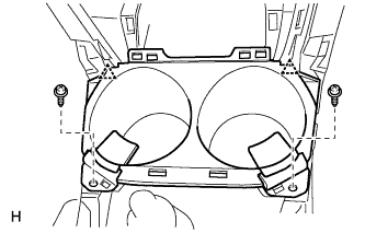
| 4. INSTALL REAR CONSOLE BOX SUB-ASSEMBLY |
Connect the connector.
Install the rear console box with the 2 bolts and attach the wire harness clamp.
Install the 2 screws.
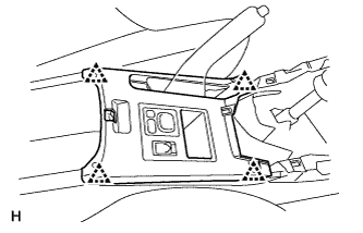
| 5. INSTALL CONSOLE REAR END PANEL |
Attach the 6 claws to install the console rear end panel.
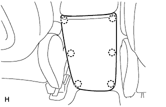
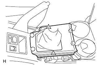
| 6. INSTALL UPPER REAR CONSOLE PANEL SUB-ASSEMBLY |
Connect the connectors.
Attach the 4 clips to install the upper rear console panel.
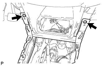
| 7. INSTALL CONSOLE CUP HOLDER BOX |
Attach the 2 clips to install the cup holder box.
Install the 2 screws.
Connect the connectors.
Attach the 2 clips and 2 claws to install the switch base.
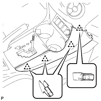
| 9. INSTALL UPPER CONSOLE PANEL SUB-ASSEMBLY |
Attach the 2 clips and 4 claws to install the upper console panel.
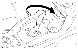
| 10. INSTALL SHIFT LEVER KNOB SUB-ASSEMBLY |
for Manual Transaxle:
Twist the shift lever knob in the direction indicated by the arrow to install it.
for Automatic Transaxle:
Twist the shift lever knob in the direction indicated by the arrow to install it.
| 11. INSTALL NO. 2 CONSOLE UPPER PANEL GARNISH |
Attach the 4 clips to install the upper panel garnish.
| 12. INSTALL NO. 1 CONSOLE UPPER PANEL GARNISH |
Attach the 4 clips to install the upper panel garnish.
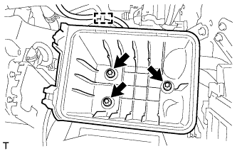
| 13. INSTALL AIR CLEANER CASE |
Install the air cleaner case with the 3 bolts.
- Torque:
- 5.0 N*m{51 kgf*cm, 44 in.*lbf}
Attach the wire harness clamp to the air cleaner case.
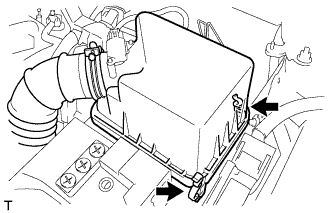
| 14. INSTALL AIR CLEANER CAP SUB-ASSEMBLY |
Insert the hinge part of the air cleaner cap and hose into the air cleaner case, and then fasten the 2 hook clamps.
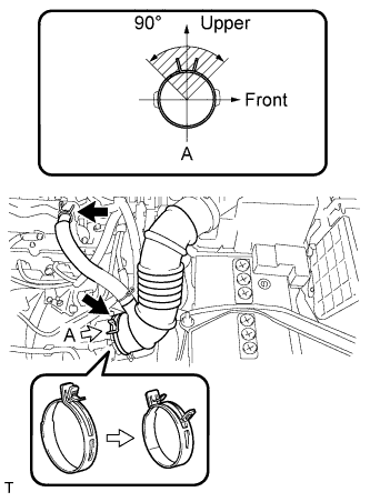
Connect the No. 1 air cleaner hose to the throttle body and push apart the tabs of the No. 1 air cleaner hose clamp.
- HINT:
- The direction of the hose clamp is indicated in the illustration.
Connect the No. 2 ventilation hose to the cylinder head cover.
Attach the clamp.
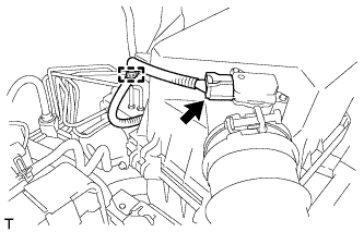
Connect the mass air flow meter connector.
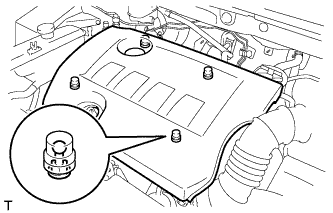
| 15. INSTALL NO. 2 CYLINDER HEAD COVER |
Attach the 4 clips to install the cover.
- NOTICE:
- Be sure to attach the clips securely.
- Do not apply excessive force or do not hit the cover to attach the clips. This may cause the cover to break.