Navigation System (For Hdd) Speaker Circuit
Navigation. Toyota Rav4. Aca30, 33, 38 Gsa33 Zsa30, 35
DESCRIPTION
WIRING DIAGRAM
INSPECTION PROCEDURE
CHECK SPEAKER
INSPECT FRONT NO. 2 SPEAKER ASSEMBLY
CHECK HARNESS AND CONNECTOR (FRONT NO. 1 SPEAKER - FRONT NO. 2 SPEAKER)
CHECK HARNESS AND CONNECTOR (NAVIGATION RECEIVER - FRONT NO. 2 SPEAKER)
INSPECT FRONT NO. 2 SPEAKER ASSEMBLY
CHECK HARNESS AND CONNECTOR (NAVIGATION RECEIVER - REAR NO. 1 SPEAKER)
INSPECT REAR NO. 1 SPEAKER ASSEMBLY
NAVIGATION SYSTEM (for HDD) - Speaker Circuit |
DESCRIPTION
A sound signal is sent from the navigation receiver assembly to the speakers through this circuit.
WIRING DIAGRAM
INSPECTION PROCEDURE
Check that the speakers sound.
ResultResult
| Proceed to
|
Front No. 1 speakers do not operate
| A
|
Front No. 2 speakers do not operate
| B
|
Rear No. 1 speakers do not operate
| C
|
All speakers do not operate
| D
|
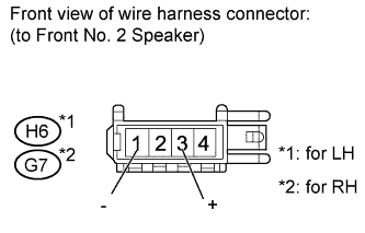
| 2.INSPECT FRONT NO. 2 SPEAKER ASSEMBLY |
Disconnect the H6*1 and/or G7*2 speaker connector.
- *1: for LH
- *2: for RH
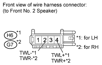
Measure the resistance according to the value(s) in the table below.
- Standard Resistance:
- for LH:
Tester Connection
| Condition
| Specified Condition
|
1 (-) - 2 (TWL-)
| Always
| Below 1 Ω
|
3 (+) - 4 (TWL+)
| Always
| Below 1 Ω
|
- for RH:
Tester Connection
| Condition
| Specified Condition
|
1 (-) - 2 (TWR-)
| Always
| Below 1 Ω
|
3 (+) - 4 (TWR+)
| Always
| Below 1 Ω
|
| | REPLACE FRONT NO. 2 SPEAKER ASSEMBLY |
|
|
| 3.CHECK HARNESS AND CONNECTOR (FRONT NO. 1 SPEAKER - FRONT NO. 2 SPEAKER) |
- *1: for LH
- *2: for RH
Disconnect the H1*1 and/or G1*2 speaker connector.
Disconnect the H6*1 and/or G7*2 speaker connector.
Measure the resistance according to the value(s) in the table below.
- Standard Resistance:
- for LH:
Tester Connection
| Condition
| Specified Condition
|
H1-1 - H6-3 (+)
| Always
| Below 1 Ω
|
H1-1 - Body ground
| Always
| 10 kΩ or higher
|
H1-2 - H6-1 (-)
| Always
| Below 1 Ω
|
H1-2 - Body ground
| Always
| 10 kΩ or higher
|
- for RH:
Tester Connection
| Condition
| Specified Condition
|
G1-1 - G7-3 (+)
| Always
| Below 1 Ω
|
G1-1 - Body ground
| Always
| 10 kΩ or higher
|
G1-2 - G7-1 (-)
| Always
| Below 1 Ω
|
G1-2 - Body ground
| Always
| 10 kΩ or higher
|
| | REPAIR OR REPLACE HARNESS OR CONNECTOR |
|
|
| 4.CHECK HARNESS AND CONNECTOR (NAVIGATION RECEIVER - FRONT NO. 2 SPEAKER) |
Disconnect the E52 navigation receiver assembly connector.
Disconnect the H6*1 and/or G7*2 speaker connector.
- *1: for LH
- *2: for RH
Measure the resistance according to the value(s) in the table below.
- Standard Resistance:
- for LH:
Tester Connection
| Condition
| Specified Condition
|
E52-2 (FL+) - H6-4 (TWL+)
| Always
| Below 1 Ω
|
E52-6 (FL-) - H6-2 (TWL-)
| Always
| Below 1 Ω
|
E52-2 (FL+) - Body ground
| Always
| 10 kΩ or higher
|
E52-6 (FL-) - Body ground
| Always
| 10 kΩ or higher
|
- for RH:
Tester Connection
| Condition
| Specified Condition
|
E52-1 (FR+) - G7-4 (TWR+)
| Always
| Below 1 Ω
|
E52-5 (FR-) - G7-2 (TWR-)
| Always
| Below 1 Ω
|
E52-1 (FR+) - Body ground
| Always
| 10 kΩ or higher
|
E52-5 (FR-) - Body ground
| Always
| 10 kΩ or higher
|
| | REPAIR OR REPLACE HARNESS OR CONNECTOR |
|
|
| 5.INSPECT FRONT NO. 2 SPEAKER ASSEMBLY |
Temporarily replace the speaker with a new or normally functioning one (RAV4_ACA30 RM0000014T700RX.html).
Check that the malfunction disappears.
- HINT:
- Connect all speaker connectors to the speakers.
- When there is a possibility that either the right or left front speaker is defective, inspect by interchanging the right one with the left one.
ResultResult
| Proceed to
|
Malfunction does not disappear
| A
|
Malfunction disappears
| B
|
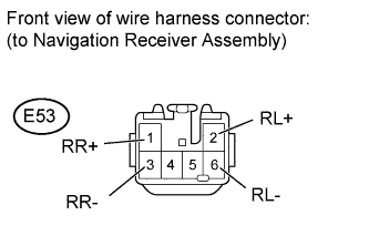
| 6.CHECK HARNESS AND CONNECTOR (NAVIGATION RECEIVER - REAR NO. 1 SPEAKER) |
Disconnect the E53 navigation receiver assembly connector.
Disconnect the J2*1 and/or I2*2 speaker connector.
- *1: for LH
- *2: for RH
Measure the resistance according to the value(s) in the table below.
- Standard Resistance:
- for LH:
Tester Connection
| Condition
| Specified Condition
|
E53-2 (RL+) - J2-1
| Always
| Below 1 Ω
|
E53-6 (RL-) - J2-2
| Always
| Below 1 Ω
|
E53-2 (RL+) - Body ground
| Always
| 10 kΩ or higher
|
E53-6 (RL-) - Body ground
| Always
| 10 kΩ or higher
|
- for RH:
Tester Connection
| Condition
| Specified Condition
|
E53-1 (RR+) - I2-1
| Always
| Below 1 Ω
|
E53-3 (RR-) - I2-2
| Always
| Below 1 Ω
|
E53-1 (RR+) - Body ground
| Always
| 10 kΩ or higher
|
E53-3 (RR-) - Body ground
| Always
| 10 kΩ or higher
|
| | REPAIR OR REPLACE HARNESS OR CONNECTOR |
|
|
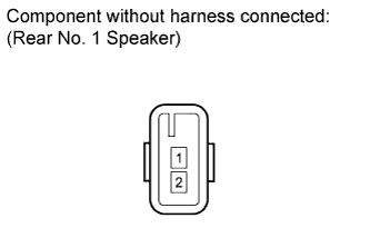
| 7.INSPECT REAR NO. 1 SPEAKER ASSEMBLY |
Disconnect the J2*1 and/or I2*2 speaker connector.
- *1: for LH
- *2: for RH
Measure the resistance according to the value(s) in the table below.
- Standard Resistance:
Tester Connection
| Condition
| Specified Condition
|
1 - 2
| Always
| 4 Ω
|