Differential Oil Seal Replacement
REMOVE FRONT DRIVE SHAFT ASSEMBLY
REMOVE TRANSMISSION CASE OIL SEAL
REMOVE MANUAL TRANSAXLE ASSEMBLY
REMOVE CLUTCH RELEASE BLEEDER SUB-ASSEMBLY
REMOVE CLUTCH RELEASE WITH BEARING CYLINDER ASSEMBLY
SECURE MANUAL TRANSAXLE ASSEMBLY
REMOVE REVERSE IDLER GEAR SHAFT BOLT
REMOVE MANUAL TRANSMISSION CASE
REMOVE REVERSE IDLER GEAR SUB-ASSEMBLY
REMOVE REVERSE SHIFT FORK SHAFT ASSEMBLY
REMOVE REVERSE SHIFT FORK
REMOVE REVERSE SHIFT ARM BRACKET ASSEMBLY
REMOVE SHIFT AND SELECT LEVER SHAFT ASSEMBLY
REMOVE INPUT SHAFT ASSEMBLY
REMOVE DIFFERENTIAL CASE ASSEMBLY
REMOVE FRONT DIFFERENTIAL CASE OIL SEAL
REMOVE FRONT TRANSAXLE CASE OIL SEAL
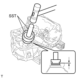
INSTALL FRONT TRANSAXLE CASE OIL SEAL
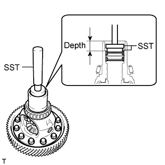
INSTALL FRONT DIFFERENTIAL CASE OIL SEAL
ADJUST OUTPUT SHAFT BEARING PRELOAD
INSTALL DIFFERENTIAL CASE ASSEMBLY
INSTALL INPUT SHAFT ASSEMBLY
INSTALL SHIFT AND SELECT LEVER SHAFT ASSEMBLY
INSTALL REVERSE SHIFT ARM BRACKET ASSEMBLY
INSTALL REVERSE SHIFT FORK
INSTALL REVERSE SHIFT FORK SHAFT ASSEMBLY
INSTALL REVERSE IDLER GEAR SUB-ASSEMBLY
INSTALL MANUAL TRANSMISSION CASE
INSTALL REVERSE IDLER GEAR SHAFT BOLT
INSTALL CLUTCH RELEASE WITH BEARING CYLINDER ASSEMBLY
REMOVE CLUTCH RELEASE BLEEDER SUB-ASSEMBLY
INSPECT CLUTCH PIPE LINE
INSTALL CLUTCH RELEASE BLEEDER SUB-ASSEMBLY
INSTALL MANUAL TRANSAXLE ASSEMBLY
INSTALL TRANSMISSION CASE OIL SEAL
INSTALL FRONT DRIVE SHAFT ASSEMBLY
INSPECT FOR OIL LEAK
Differential Oil Seal -- Replacement |
- NOTICE:
- When the transaxle is removed, be sure to use a new clutch release with bearing cylinder and new installation bolts. Removal of the transaxle allows the compressed clutch release with bearing cylinder to return to its original position, and dust could damage the seal of the clutch release with bearing cylinder, possibly causing clutch fluid leaks.
| 1. REMOVE FRONT DRIVE SHAFT ASSEMBLY |
Remove the front drive shaft assembly (RAV4_ACA30 RM00000226Q008X.html).
| 2. REMOVE TRANSMISSION CASE OIL SEAL |
Using SST, remove the transmission case oil seal.
- SST
- 09308-00010
| 3. REMOVE MANUAL TRANSAXLE ASSEMBLY |
Remove the manual transaxle assembly (RAV4_ACA30 RM000001B3W02WX.html).
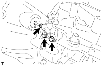
| 4. REMOVE CLUTCH RELEASE BLEEDER SUB-ASSEMBLY |
Using a union nut wrench, separate the clutch release bleeder sub-assembly from the clutch release cylinder to bleeder tube.
Remove the 2 bolts and clutch release bleeder sub-assembly from the manual transaxle assembly.
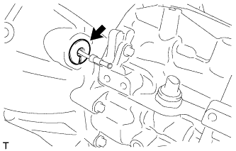
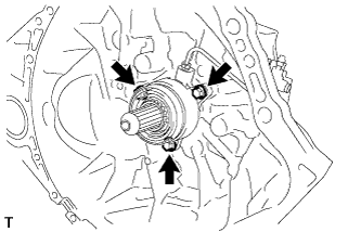
| 5. REMOVE CLUTCH RELEASE WITH BEARING CYLINDER ASSEMBLY |
Remove the clutch tube boot from the manual transaxle assembly.
Remove the 3 bolts and clutch release with bearing cylinder assembly and clutch release cylinder to bleeder tube.
Using a union nut wrench, remove the clutch release cylinder to bleeder tube from the clutch release with bearing cylinder assembly.
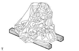
| 6. SECURE MANUAL TRANSAXLE ASSEMBLY |
Place the manual transaxle on wooden blocks.
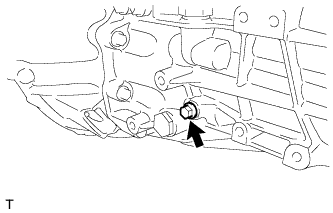
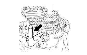
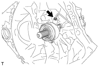
| 7. REMOVE REVERSE IDLER GEAR SHAFT BOLT |
Remove the reverse idler gear shaft bolt and gasket from the manual transmission case.
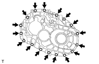
| 8. REMOVE MANUAL TRANSMISSION CASE |
Remove the 17 bolts.
Using a screwdriver with its tip wrapped with protective tape, separate the manual transmission case from the front transaxle case.
Text in Illustration*1
| Protective Tape
|
- NOTICE:
- Do not damage the manual transmission case.
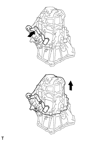
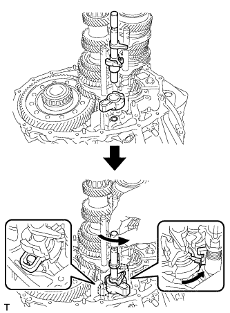
Turn the outer No. 1 shift lever clockwise until it comes into contact with the boss.
Push the outer No. 1 shift lever and remove the manual transmission case.
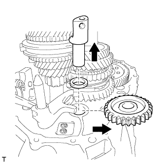
| 9. REMOVE REVERSE IDLER GEAR SUB-ASSEMBLY |
Remove the reverse idler gear, thrust washer and reverse idler gear shaft from the front transaxle case.
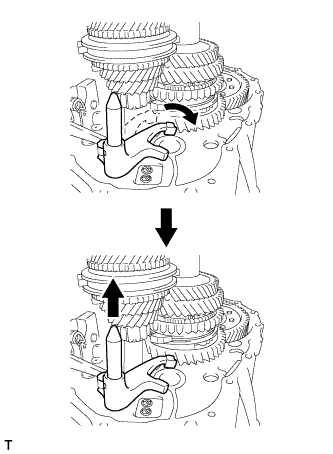
| 10. REMOVE REVERSE SHIFT FORK SHAFT ASSEMBLY |
Turn the reverse shift fork shaft clockwise and remove it from the front transaxle case.
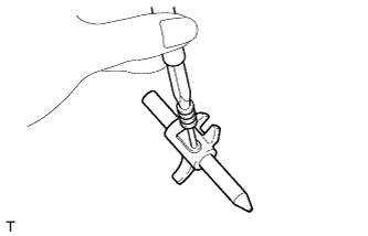
| 11. REMOVE REVERSE SHIFT FORK |
Using a 5 mm pin punch and hammer, tap out the reverse shift fork slotted spring pin.
Remove the reverse shift fork from the reverse shift fork shaft.
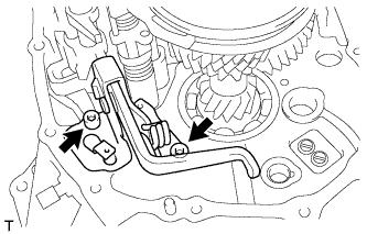
| 12. REMOVE REVERSE SHIFT ARM BRACKET ASSEMBLY |
Using a 6 mm hexagon socket wrench, remove the 2 bolts and reverse shift arm bracket from the front transaxle case.
| 13. REMOVE SHIFT AND SELECT LEVER SHAFT ASSEMBLY |
Turn the shift and select lever shaft clockwise and remove it from the front transaxle case.
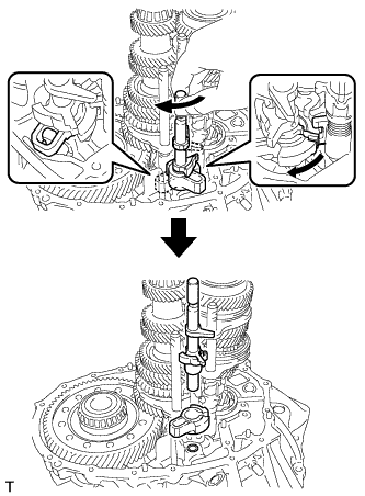
| 14. REMOVE INPUT SHAFT ASSEMBLY |
Remove the input shaft assembly, output shaft assembly and 2 gear shift fork shaft assemblies from the front transaxle case.
Remove the output shaft assembly together with the No. 1 gear shift fork shaft assembly from the input shaft assembly.
Remove the No. 1 gear shift fork shaft assembly from the output shaft assembly.
Remove the No. 2 gear shift fork shaft assemblies from the input shaft assembly.
| 15. REMOVE DIFFERENTIAL CASE ASSEMBLY |
Remove the differential case from the front transaxle case.
| 16. REMOVE FRONT DIFFERENTIAL CASE OIL SEAL |
Using SST, remove the front differential case oil seal from the front differential case.
- SST
- 09308-00010
| 17. REMOVE FRONT TRANSAXLE CASE OIL SEAL |
Using SST, remove the front transaxle case oil seal.
- SST
- 09308-00010
| 18. INSTALL FRONT TRANSAXLE CASE OIL SEAL |
Coat the lip of a new oil seal with MP grease.
Using SST and a hammer, tap in the front transaxle case oil seal to the front transaxle case.
- SST
- 09710-30050
09950-70010(09951-07100)
- Standard depth:
- 5.5 to 6.5 mm (0.217 to 0.256 in.)
- NOTICE:
- Do not damage the oil seal lip.
| 19. INSTALL FRONT DIFFERENTIAL CASE OIL SEAL |
Coat the lip of a new oil seal with MP grease.
Using SST and a hammer, tap in a new front differential case oil seal to the front differential case.
- SST
- 09950-60010(09951-00330,09951-00410,09952-06010)
09950-70010(09951-07100)
- Standard depth:
- 21.5 to 22.5 mm (0.846 to 0.885 in.)
- NOTICE:
- Do not damage the oil seal lip.
| 20. ADJUST OUTPUT SHAFT BEARING PRELOAD |
Coat the differential case assembly with gear oil and install it to the front transaxle case.
Coat the output shaft assembly with gear oil and install it to the front transaxle case.
Install the manual transmission case with the 17 bolts.
- Torque:
- 29 N*m{300 kgf*cm, 22 ft.*lbf}
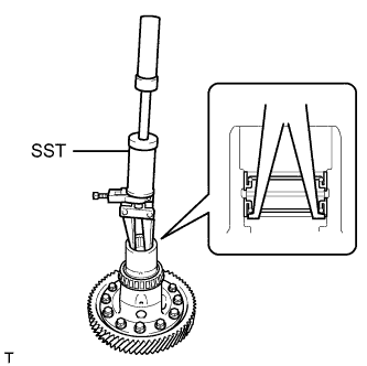
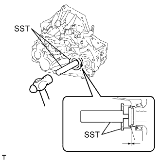
Using SST and a torque wrench, turn the differential case assembly clockwise and counterclockwise 2 or 3 times to allow the bearings to settle.
- SST
- 09564-50010
Using SST and a torque wrench, measure the preload (value A). Calculate the rear output shaft bearing preload using the following formula.
- SST
- 09564-50010
- Formula:
- Value A - Differential side bearing preload = Output shaft bearing preload
- Preload (at starting):
- New bearing:
- 3.17 to 6.35 N*m (32 to 65 kgf*cm, 28 to 56 in.*lbf)
- Used bearing:
- 2.61 to 5.24 N*m (27 to 53 kgf*cm, 23 to 46 in.*lbf)
Text in Illustration*1
| Bearing Shim
|
If the preload is not as specified, replace the rear output shaft bearing shim with one of a different thickness. Use the table below to select a rear output shaft bearing shim which will ensure that the preload is within the specification.
- Standard Bearing Shim Thickness:
Mark
| Specified Condition
| Mark
| Specified Condition
|
A
| 1.30 mm (0.511 in.)
| P
| 1.95 mm (0.768 in.)
|
B
| 1.35 mm (0.531 in.)
| Q
| 2.00 mm (0.787 in.)
|
C
| 1.40 mm (0.551 in.)
| R
| 2.05 mm (0.807 in.)
|
D
| 1.45 mm (0.571 in.)
| S
| 2.10 mm (0.827 in.)
|
E
| 1.50 mm (0.591 in.)
| T
| 2.15 mm (0.846 in.)
|
F
| 1.55 mm (0.610 in.)
| U
| 2.20 mm (0.866 in.)
|
G
| 1.60 mm (0.630 in.)
| V
| 2.25 mm (0.886 in.)
|
H
| 1.65 mm (0.650 in.)
| W
| 2.30 mm (0.906 in.)
|
J
| 1.70 mm (0.669 in.)
| X
| 2.35 mm (0.925 in.)
|
K
| 1.75 mm (0.689 in.)
| Y
| 2.40 mm (0.945 in.)
|
L
| 1.80 mm (0.709 in.)
| Z
| 2.45 mm (0.965 in.)
|
M
| 1.85 mm (0.728 in.)
| 1
| 2.50 mm (0.984 in.)
|
N
| 1.90 mm (0.748 in.)
| -
| -
|
- HINT:
- Select a thicker bearing shim to increase the preload, or a thinner bearing shim to decrease the preload.
Remove the 17 bolts and manual transmission case.
Remove the output shaft assembly from the front transaxle case.
Remove the differential case from the front transaxle case.
Replace the installed rear output shaft bearing shim with the one selected above.
| 21. INSTALL DIFFERENTIAL CASE ASSEMBLY |
Coat the differential case tapered roller bearing with gear oil and install it to the front transaxle case.
| 22. INSTALL INPUT SHAFT ASSEMBLY |
Apply gear oil to all sliding and rotating parts.
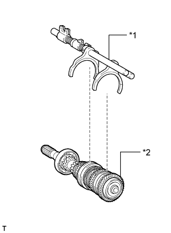
Coat the No. 1 gear shift fork shaft with gear oil and install it onto the output shaft assembly.
Text in Illustration*1
| No. 1 Gear Shift Fork Shaft
|
*2
| Output Shaft
|
Coat the No. 2 gear shift fork shaft with gear oil and install it onto the input shaft assembly.
Text in Illustration*1
| No. 2 Gear Shift Fork Shaft
|
*2
| Input shaft
|
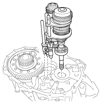
Temporarily install the output shaft with No. 1 gear shift fork shaft to the input shaft assembly, and tie them with a rope or string.
Install the input shaft assembly, output shaft assembly and 2 gear shift fork shaft assemblies to the front transaxle case.
| 23. INSTALL SHIFT AND SELECT LEVER SHAFT ASSEMBLY |
Install the shift interlock plate and shift and select lever shaft assembly to the front transaxle case, and then turn them counterclockwise.
- HINT:
- When installing the shift interlock plate, make sure to engage it with the inner select lever.
| 24. INSTALL REVERSE SHIFT ARM BRACKET ASSEMBLY |
Coat the threads of the 2 bolts with adhesive, and then install the reverse shift arm bracket with the 2 bolts.
- Adhesive:
- Toyota Genuine Adhesive 1344, Three Bond 1344 or equivalent
- Torque:
- 17 N*m{175 kgf*cm, 13 ft.*lbf}
| 25. INSTALL REVERSE SHIFT FORK |
Using a 5 mm pin punch and a hammer, install the reverse shift fork slotted pin onto the reverse shift fork shaft.
- Standard driven in depth:
- -0.5 to 0.5 mm (-0.0196 to 0.0196 in.)
- NOTICE:
- Confirm the installation direction.
| 26. INSTALL REVERSE SHIFT FORK SHAFT ASSEMBLY |
Coat the reverse shift fork shaft assembly with gear oil and install it onto the front transaxle case.
| 27. INSTALL REVERSE IDLER GEAR SUB-ASSEMBLY |
Coat the reverse idler gear sub-assembly, thrust washer and reverse idler gear shaft with gear oil, and install them as shown in the illustration.
Text in Illustration*1
| Case Hole
|
*2
| I-groove mark of the reverse idler gear shaft
|
- HINT:
- Raise the edge of the reverse shift arm bracket assembly and connect the reverse shift arm bracket assembly to the reverse shift fork shaft assembly.
- NOTICE:
- Using the bolt hole of the case for reference, align the I-groove mark of the reverse idler gear shaft within the range shown (approximately 20°).
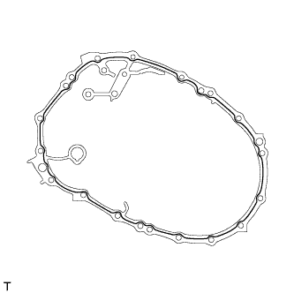
| 28. INSTALL MANUAL TRANSMISSION CASE |
Apply seal packing to the manual transmission case as shown in the illustration.
- Seal packing:
- Toyota Genuine Seal Packing 1281, Three Bond 1281 or equivalent
- Seal packing diameter:
- 1.2 mm (0.0472 in.)
- NOTICE:
- Remove any oil from the contact surfaces.
- Assemble the parts within 10 minutes of application. Otherwise, the packing (FIPG) material must be removed and reapplied.
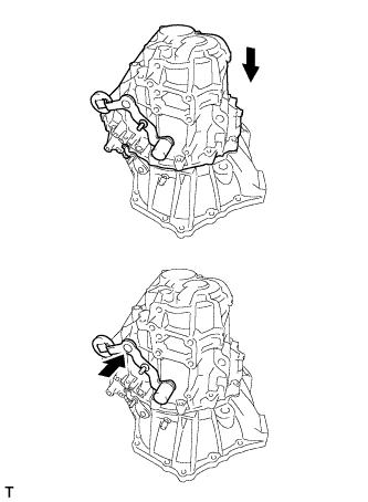
Push the outer No. 1 shift lever and install the manual transmission case.
- HINT:
- Pushing the outer No. 1 shift lever allows the manual transmission case to be installed.
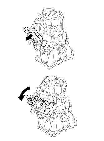
Turn the outer No. 1 shift lever counterclockwise and then pull it.
Install the manual transmission case with the 17 bolts.
- Torque:
- 29 N*m{300 kgf*cm, 22 ft.*lbf}
| 29. INSTALL REVERSE IDLER GEAR SHAFT BOLT |
Install a new gasket and the reverse idler gear shaft bolt to the manual transmission case.
- Torque:
- 30 N*m{306 kgf*cm, 22 ft.*lbf}
| 30. INSTALL CLUTCH RELEASE WITH BEARING CYLINDER ASSEMBLY |
Temporarily install the clutch release cylinder to bleeder tube to a new clutch release with bearing cylinder assembly.
Clean and degrease all installation surfaces for the clutch release with bearing cylinder assembly.
Install the clutch release with bearing cylinder assembly with 3 new bolts.
- Torque:
- 23 N*m{229 kgf*cm, 17 ft.*lbf}
- NOTICE:
- The clutch release with bearing cylinder and installation bolts cannot be reused and must be replaced with new ones.
- Clean and degrease all installation surfaces and make sure the clutch release with bearing cylinder fits securely with the transaxle during installation. The first bolt should be tightened by hand while holding the clutch release with bearing cylinder.
- Make sure that none of the clutch spline grease adheres to the clutch release with bearing cylinder.
- The clutch release with bearing cylinder cannot be disassembled.
Install the clutch tube boot to the manual transaxle assembly.
Temporarily install the clutch release cylinder to bleeder tube to the clutch release bleeder sub-assembly.
Temporarily install the clutch release bleeder sub-assembly with the 2 bolts.
Using a union nut wrench, install the clutch release cylinder to bleeder tube to the clutch release with bearing cylinder assembly.
- Torque:
- 15 N*m{155 kgf*cm, 11 ft.*lbf}
- NOTICE:
- Use the formula to calculate special torque values for situations where a union nut wrench is combined with a torque wrench (RAV4_ACA30 RM0000018UO018X.html).
Apply clutch spline grease to the input shaft spline.
- Grease:
- Toyota Genuine Clutch Spline Grease or equivalent
Text in Illustration*1
| Clutch Spline Grease
|
| 31. REMOVE CLUTCH RELEASE BLEEDER SUB-ASSEMBLY |
Separate the clutch release cylinder to bleeder tube from the clutch release bleeder sub-assembly.
Remove the 2 bolts and clutch release bleeder sub-assembly.
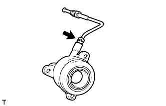
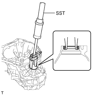
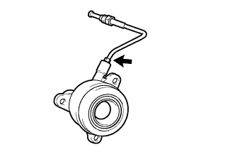
| 32. INSPECT CLUTCH PIPE LINE |
Using SST, apply a pressure of 100 kPa (1.0 kgf/cm2, 15 psi) to the clutch pipe location shown in the illustration and confirm that pressure is maintained for 15 seconds or more.
- SST
- 09992-00242
If the pressure drops, replace the clutch release cylinder to bleeder tube.
| 33. INSTALL CLUTCH RELEASE BLEEDER SUB-ASSEMBLY |
Temporarily install the clutch release cylinder to bleeder tube to the clutch release bleeder sub-assembly.
Install the clutch release bleeder sub-assembly with the 2 bolts.
- Torque:
- 17 N*m{170 kgf*cm, 12 ft.*lbf}
Using a union nut wrench, install the clutch release cylinder to bleeder tube.
- Torque:
- 15 N*m{155 kgf*cm, 11 ft.*lbf}
- NOTICE:
- Use the formula to calculate special torque values for situations where a union nut wrench is combined with a torque wrench (RAV4_ACA30 RM0000018UO018X.html).
| 34. INSTALL MANUAL TRANSAXLE ASSEMBLY |
the manual transaxle assembly (RAV4_ACA30 RM000001B3U02WX.html).
| 35. INSTALL TRANSMISSION CASE OIL SEAL |
Coat the lip of a new oil seal with MP grease.
Using SST and a hammer, tap in the transmission case oil seal to the manual transmission case.
- SST
- 09608-32010
09950-70010(09951-07100)
- Standard depth:
- -0.5 to 0.5 mm (-0.0197 to 0.0196 in.)
- NOTICE:
- Do not damage the oil seal lip.
| 36. INSTALL FRONT DRIVE SHAFT ASSEMBLY |
Install the front drive shaft assembly (RAV4_ACA30 RM00000226O008X.html).