Can Communication System -- Terminals Of Ecu |
- NOTICE:
- Turn the ignition switch off before measuring the resistance of the main wire and the branch wire.
- After the ignition switch is turned off, check that the key reminder warning system and light reminder buzzer are not in operation.
- Before measuring the resistance, leave the vehicle for at least 1 minute and do not operate the ignition switch, any switches or doors. If doors need to be opened in order to check connectors, open the doors and leave them open.
- w/ Navigation System (for HDD):
After the ignition switch is turned off, the HDD navigation system requires approximately a minute to record various types of memory and settings. As a result, after turning the ignition switch off, wait a minute or higher before disconnecting the cable from the negative (-) battery terminal.
- HINT:
- Operating the ignition switch, any switches or any doors triggers related ECU and sensor communication with the CAN, which causes resistance variation.
| JUNCTION CONNECTOR (for LHD) |
No. 1 Junction Connector

No. 1 Junction Connector Wiring Color Connect to CANH (A80-1) R - Brake actuator (skid control ECU)*1
- ABS and traction actuator (skid control ECU)*2
CANL (A80-12) W CANH (A80-2) Y ECM CANL (A80-13) W CANH (A80-3) L No. 2 junction connector CANL (A80-14) W - *1: w/ Anti-lock Brake System
- *2: w/ Vehicle Stability Control System
- Brake actuator (skid control ECU)*1
No. 2 Junction Connector
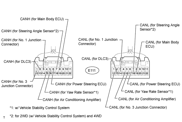
No. 2 Junction Connector Wiring Color Connect to CANH (E111-1) SB No. 3 junction connector CANL (E111-12) W CANH (E111-2) B DLC3 CANL (E111-13) W CANH (E111-3) L No. 1 junction connector CANL (E111-14) W CANH (E111-4) V Air conditioning amplifier CANL (E111-15) W CANH (E111-5) L Yaw rate sensor*1 CANL (E111-16) W CANH (E111-6) Y Power steering ECU CANL (E111-17) W CANH (E111-7) BR Steering angle sensor*2 CANL (E111-18) W CANH (E111-8) R Main body ECU CANL (E111-19) W - *1: w/ Vehicle Stability Control System
- *2: for 2WD (w/ Vehicle Stability Control System) and 4WD
- *1: w/ Vehicle Stability Control System
No. 3 Junction Connector

No. 3 Junction Connector Wiring Color Connect to CANH (E115-1) B Center airbag sensor assembly CANL (E115-12) W CANH (E115-2) V No. 4 junction connector CANL (E115-13) W CANH (E115-3) SB No. 2 junction connector CANL (E115-14) W No. 4 Junction Connector
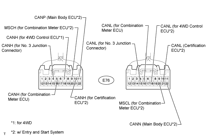
No. 4 Junction Connector Wiring Color Connect to CANH (E76-4) V No. 3 junction connector CANL (E76-15) W CANH (E76-5) G Combination meter ECU CANL (E76-16) W CANH (E76-7) P 4WD control ECU*1 CANL (E76-18) W MSCH (E76-9) LG Combination meter ECU*2 MSCL (E76-20) W CANH (E76-10) SB Certification ECU*2 CANL (E76-21) W CANP (E76-11) Y Main body ECU*2 CANN (E76-22) W - *1: for 4WD
- *2: w/ Entry and Start System
- *1: for 4WD
| JUNCTION CONNECTOR (for RHD) |
No. 1 Junction Connector
No. 1 Junction Connector Wiring Color Connect to CANH (A80-1) R - Brake actuator (skid control ECU)*1
- ABS and traction actuator (skid control ECU)*2
CANL (A80-12) W CANH (A80-2) Y ECM CANL (A80-13) W CANH (A80-3) L No. 2 junction connector CANL (A80-14) W - *1: w/ Anti-lock Brake System
- *2: w/ Vehicle Stability Control System
- Brake actuator (skid control ECU)*1
No. 2 Junction Connector

No. 2 Junction Connector Wiring Color Connect to CANH (E112-1) SB No. 3 junction connector CANL (E112-12) W CANH (E112-2) L Yaw rate sensor* CANL (E112-13) W CANH (E112-4) L No. 1 junction connector CANL (E112-15) W CANH (E112-5) R Main body ECU CANL (E112-16) W - *: w/ Vehicle Stability Control System
- *: w/ Vehicle Stability Control System
No. 3 Junction Connector

No. 3 Junction Connector Wiring Color Connect to CANH (E115-1) B Center airbag sensor assembly CANL (E115-12) W CANH (E115-2) V Air conditioning amplifier CANL (E115-13) W CANH (E115-3) SB No. 2 junction connector CANL (E115-14) W CANH (E115-4) Y Power steering ECU CANL (E115-15) W CANH (E115-5) V No. 4 junction connector CANL (E115-16) W No. 4 Junction Connector
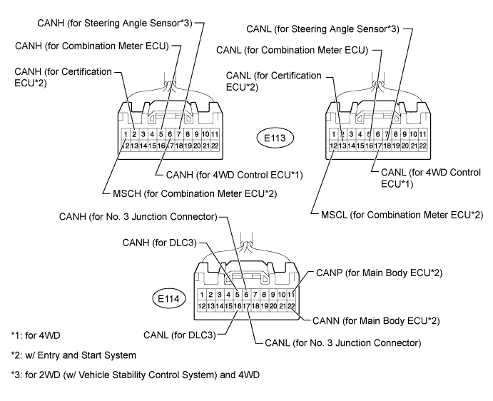
No. 4 Junction Connector Wiring Color Connect to MSCH (E113-1) LG Combination meter ECU*2 MSCL (E113-12) W CANH (E113-2) SB Certification ECU*2 CANL (E113-13) W CANH (E113-5) G Combination meter ECU CANL (E113-16) W CANH (E113-6) P 4WD control ECU*1 CANL (E113-17) W CANH (E113-7) BR Steering angle sensor*3 CANL (E113-18) W CANH (E114-5) B DLC3 CANL (E114-16) W CANH (E114-6) V No. 3 junction connector CANL (E114-17) W CANP (E114-11) Y Main body ECU*2 CANN (E114-22) W - *1: for 4WD
- *2: w/ Entry and Start System
- *3: for 2WD (w/ Vehicle Stability Control System) and 4WD
- *1: for 4WD
| CHECK DLC3 |
Disconnect the cable from the negative (-) battery terminal before measuring the resistances of the main wire and the branch wire.
- NOTICE:
- w/ Navigation System (for HDD):
After the ignition switch is turned off, the HDD navigation system requires approximately a minute to record various types of memory and settings. As a result, after turning the ignition switch off, wait a minute or higher before disconnecting the cable from the negative (-) battery terminal. - When disconnecting the cable, some systems need to be initialized after the cable is reconnected.
Measure the resistance according to the value(s) in the table below.
Symbols (Terminal No.) Wiring Color Condition Specified Condition CANH (E16-6) - CANL (E16-14) B - W Ignition switch off 54 to 69 Ω CANH (E16-6) - CG (E16-4) B - BR Ignition switch off 200 Ω or higher CANL (E16-14) - CG (E16-4) W - BR Ignition switch off 200 Ω or higher CANH (E16-6) - BAT (E16-16) B - L Ignition switch off 6 kΩ or higher CANL (E16-14) - BAT (E16-16) W - L Ignition switch off 6 kΩ or higher
 |
| CHECK BRAKE ACTUATOR (SKID CONTROL ECU) (w/ Anti-lock Brake System) |
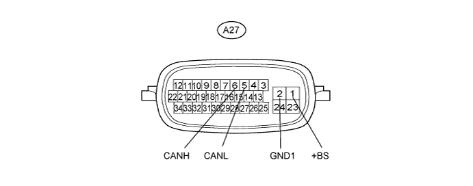
Disconnect the A27 ECU connector.
Measure the resistance according to the value(s) in the table below.
Symbols (Terminal No.) Wiring Color Condition Specified Condition CANH (A27-6) - CANL (A27-5) R - W Ignition switch off 54 to 69 Ω CANH (A27-6) - GND1 (A27-2) R - W-B Ignition switch off 200 Ω or higher CANL (A27-5) - GND1 (A27-2) W - W-B Ignition switch off 200 Ω or higher CANH (A27-6) - +BS (A27-1) R - W Ignition switch off 6 kΩ or higher CANL (A27-5) - +BS (A27-1) W - W Ignition switch off 6 kΩ or higher
| CHECK ABS AND TRACTION ACTUATOR (SKID CONTROL ECU) (w/ Vehicle Stability Control System) |
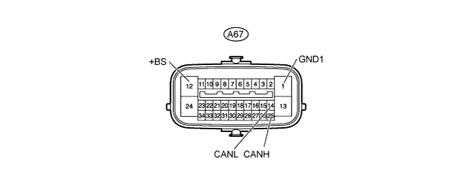
Disconnect the A67 ECU connector.
Measure the resistance according to the value(s) in the table below.
Symbols (Terminal No.) Wiring Color Condition Specified Condition CANH (A67-25) - CANL (A67-14) R - W Ignition switch off 54 to 69 Ω CANH (A67-25) - GND1 (A67-1) R - W-B Ignition switch off 200 Ω or higher CANL (A67- 14) - GND1 (A67-1) W - W-B Ignition switch off 200 Ω or higher CANH (A67-25) - +BS (A67-12) R - W Ignition switch off 6 kΩ or higher CANL (A67-14) - +BS (A67-12) W - W Ignition switch off 6 kΩ or higher
| CHECK STEERING ANGLE SENSOR (for 2WD [w/ Vehicle Stability Control System] and for 4WD) |

Disconnect the E95 sensor connector.
Measure the resistance according to the value(s) in the table below.
Symbols (Terminal No.) Wiring Color Condition Specified Condition CANH (E95-3) - CANL (E95-2) BR - W Ignition switch off 54 to 69 Ω CANH (E95-3) - ESS (E95-1) BR - W-B Ignition switch off 200 Ω or higher CANL (E95-2) - ESS (E95-1) W - W-B Ignition switch off 200 Ω or higher CANH (E95-3) - BAT (E95-5) BR - R Ignition switch off 6 kΩ or higher CANL (E95-2) - BAT (E95-5) W - R Ignition switch off 6 kΩ or higher
| CHECK YAW RATE SENSOR (w/ Vehicle Stability Control System) |

Disconnect the K25 sensor connector.
Measure the resistance according to the value(s) in the table below.
Symbols (Terminal No.) Wiring Color Condition Specified Condition CANH (K25-3) - CANL (K25-2) L - W Ignition switch off 54 to 69 Ω CANH (K25-3) - GND (K25-1) L - W-B Ignition switch off 200 Ω or higher CANL (K25-2) - GND (K25-1) W - W-B Ignition switch off 200 Ω or higher CANH (K25-3) - BAT (E16-16) L - L Ignition switch off 6 kΩ or higher CANL (K25-2) - BAT (E16-16) W - L Ignition switch off 6 kΩ or higher
| CHECK AIR CONDITIONING AMPLIFIER (for Automatic Air Conditioning System) |

Disconnect the E41 amplifier connector.
Measure the resistance according to the value(s) in the table below.
Symbols (Terminal No.) Wiring Color Condition Specified Condition CANH (E41-11) - CANL (E41-12) V - W Ignition switch off 54 to 69 Ω CANH (E41-11) - GND (E41-14) V - W-B Ignition switch off 200 Ω or higher CANL (E41-12) - GND (E41-14) W - W-B Ignition switch off 200 Ω or higher CANH (E41-11) - B (E41-21) V - R Ignition switch off 6 kΩ or higher CANL (E41-12) - B (E41-21) W - R Ignition switch off 6 kΩ or higher
| CHECK AIR CONDITIONING AMPLIFIER (for Manual Air Conditioning System) |

Disconnect the E42 amplifier connector.
Measure the resistance according to the value(s) in the table below.
Symbols (Terminal No.) Wiring Color Condition Specified Condition CANH (E42-8) - CANL (E42-9) V - W Ignition switch off 54 to 69 Ω CANH (E42-8) - GND (E42-24) V - W-B Ignition switch off 200 Ω or higher CANL (E42-9) - GND (E42-24) W - W-B Ignition switch off 200 Ω or higher CANH (E42-8) - BAT (E16-16) V - L Ignition switch off 6 kΩ or higher CANL (E42-9) - BAT (E16-16) W - L Ignition switch off 6 kΩ or higher
| CHECK ECM |

Disconnect the A12 and B96*1 or B32*2,*3 ECM connectors.
- *1: for 2GR-FE
- *2: for 1AZ-FE, 2AZ-FE
- *3: for 3ZR-FAE
- *1: for 2GR-FE
Measure the resistance according to the value(s) in the table below.
for 2GR-FE Symbols (Terminal No.) Wiring Color Condition Specified Condition CANH (A12-41) - CANL (A12-49) Y - W Ignition switch off 108 to 132 Ω CANH (A12-41) - E1 (B96-81) Y - BR Ignition switch off 200 Ω or higher CANL (A12-49) - E1 (B96-81) W - BR Ignition switch off 200 Ω or higher CANH (A12-41) - BATT (A12-20) Y - W Ignition switch off 6 kΩ or higher CANL (A12-49) - BATT (A12-20) W - W Ignition switch off 6 kΩ or higher for 1AZ-FE, 2AZ-FE Symbols (Terminal No.) Wiring Color Condition Specified Condition CANH (A12-41) - CANL (A12-49) Y - W Ignition switch off 108 to 132 Ω CANH (A12-41) - E1 (B32-104) Y - BR Ignition switch off 200 Ω or higher CANL (A12-49) - E1 (B32-104) W - BR Ignition switch off 200 Ω or higher CANH (A12-41) - BATT (A12-20) Y - W Ignition switch off 6 kΩ or higher CANL (A12-49) - BATT (A12-20) W - W Ignition switch off 6 kΩ or higher for 3ZR-FAE Symbols (Terminal No.) Wiring Color Condition Specified Condition CANH (A12-8) - CANL (A12-9) Y - W Ignition switch off 108 to 132 Ω CANH (A12-8) - E1 (B32-105) Y - BR Ignition switch off 200 Ω or higher CANL (A12-9) - E1 (B32-105) W - BR Ignition switch off 200 Ω or higher CANH (A12-8) - BATT (A12-20) Y - W Ignition switch off 6 kΩ or higher CANL (A12-9) - BATT (A12-20) W - W Ignition switch off 6 kΩ or higher
| CHECK CENTER AIRBAG SENSOR ASSEMBLY |

Disconnect the E49 sensor connector.
Measure the resistance according to the value(s) in the table below.
Symbols (Terminal No.) Wiring Color Condition Specified Condition CANH (E49-13) - CANL (E49-22) B - W Ignition switch off 54 to 69 Ω CANH (E49-13) - E1 (E49-25) B - W-B Ignition switch off 200 Ω or higher CANL (E49-22) - E1 (E49-25) W - W-B Ignition switch off 200 Ω or higher CANH (E49-13) - BAT (E16-16) B - L Ignition switch off 6 kΩ or higher CANL (E49-22) - BAT (E16-16) W - L Ignition switch off 6 kΩ or higher
| CHECK POWER STEERING ECU |

Disconnect the A2 and E21 ECU connectors.
Measure the resistance according to the value(s) in the table below.
Symbols (Terminal No.) Wiring Color Condition Specified Condition CANH (E21-2) - CANL (E21-8) Y - W Ignition switch off 54 to 69 Ω CANH (E21-2) - PGND (A2-2) Y - W-B Ignition switch off 200 Ω or higher CANL (E21-8) - PGND (A2-2) W - W-B Ignition switch off 200 Ω or higher CANH (E21-2) - PIG (A2-1) Y - W-B*1
Y - L*2Ignition switch off 6 kΩ or higher CANL (E21-8) - PIG (A2-1) W - W-B*1
W - L*2Ignition switch off 6 kΩ or higher - *1: for LHD
- *2: for RHD
- *1: for LHD
| CHECK COMBINATION METER ECU |
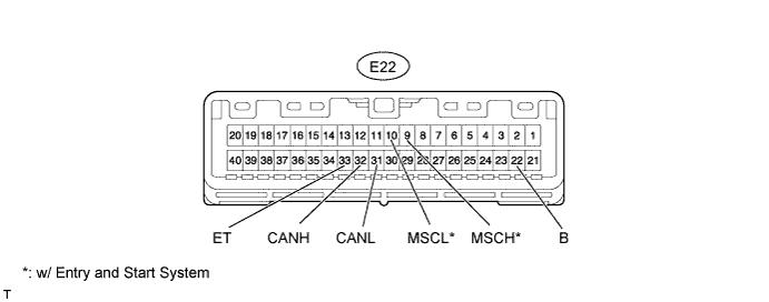
Disconnect the E22 ECU connector.
Measure the resistance according to the value(s) in the table below.
Symbols (Terminal No.) Wiring Color Condition Specified Condition CANH (E22-32) - CANL (E22-31) G - W Ignition switch off 108 to 132 Ω CANH (E22-32) - ET (E22-33) G - BR Ignition switch off 200 Ω or higher CANL (E22-31) - ET (E22-33) W - BR Ignition switch off 200 Ω or higher CANH (E22-32) - B (E22-22) G - R Ignition switch off 6 kΩ or higher CANL (E22-31) - B (E22-22) W - R Ignition switch off 6 kΩ or higher MSCH (E22-9) - MSCL (E22-10)* LG - W Ignition switch off 108 to 132 Ω MSCH (E22-9) - ET (E22-33)* LG - BR Ignition switch off 200 Ω or higher MSCL (E22-10) - ET (E22-33)* W - BR Ignition switch off 200 Ω or higher MSCH (E22-9) - B (E22-22)* LG - R Ignition switch off 6 kΩ or higher MSCL (E22-10) - B (E22-22)* W - R Ignition switch off 6 kΩ or higher - *: w/ Entry and Start System
- *: w/ Entry and Start System
| CHECK CERTIFICATION ECU (w/ Entry and Start System) |

Disconnect the E63 ECU connector.
Measure the resistance according to the value(s) in the table below.
Symbols (Terminal No.) Wiring Color Condition Specified Condition CANH (E63-27) - CANL (E63-28) SB - W Ignition switch off 54 to 69 Ω CANH (E63-27) - E (E63-17) SB- W-B Ignition switch off 200 Ω or higher CANL (E63-28) - E (E63-17) W - W-B Ignition switch off 200 Ω or higher CANH (E63-27) - +B (E63-1) SB - R Ignition switch off 6 kΩ or higher CANL (E63-28) - +B (E63-1) W - R Ignition switch off 6 kΩ or higher
| CHECK MAIN BODY ECU |


Disconnect the E19*1, E20, IB*2 and IE ECU connectors.
- *1: w/ Entry and Start System
- *2: w/o Entry and Start System
- *1: w/ Entry and Start System
Measure the resistance according to the value(s) in the table below.
w/ Entry and Start System Symbols (Terminal No.) Wiring Color Condition Specified Condition CANH (E20-15) - CANL (E20-16) R - W Ignition switch off 54 to 69 Ω CANH (E20-15) - GND1 (IE-17) R - W-B Ignition switch off 200 Ω or higher CANL (E20-16) - GND1 (IE-17) W - W-B Ignition switch off 200 Ω or higher CANH (E20-15) - AM1 (E19-1) R - W Ignition switch off 6 kΩ or higher CANL (E20-16) - AM1 (E19-1) W - W Ignition switch off 6 kΩ or higher CANP (E19-11) - CANN (E19-12) Y - W Ignition switch off 108 to 132 Ω CANP (E19-11) - GND1 (IE-17) Y - W-B Ignition switch off 200 Ω or higher CANN (E19-12) - GND1 (IE-17) W - W-B Ignition switch off 200 Ω or higher CANP (E19-11) - AM1 (E19-1) Y - W Ignition switch off 6 kΩ or higher CANN (E19-12) - AM1 (E19-1) W - W Ignition switch off 6 kΩ or higher w/o Entry and Start System Symbols (Terminal No.) Wiring Color Condition Specified Condition CANH (E20-15) - CANL (E20-16) R - W Ignition switch off 54 to 69 Ω CANH (E20-15) - GND1 (IE-17) R - W-B Ignition switch off 200 Ω or higher CANL (E20-16) - GND1 (IE-17) W - W-B Ignition switch off 200 Ω or higher CANH (E20-15) - BECU (IB-30) R - R Ignition switch off 6 kΩ or higher CANL (E20-16) - BECU (IB-30) W - R Ignition switch off 6 kΩ or higher
| CHECK 4WD CONTROL ECU (for 4WD) |
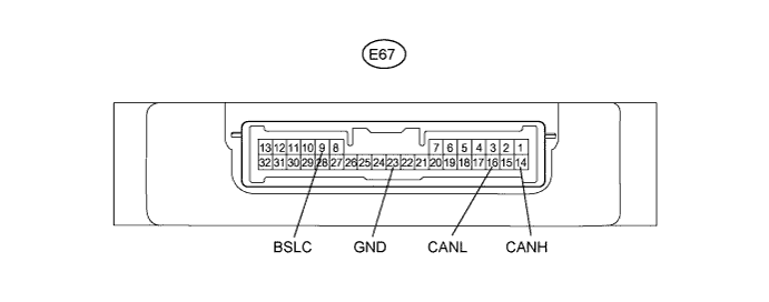
Disconnect the E67 ECU connector.
Measure the resistance according to the value(s) in the table below.
Symbols (Terminal No.) Wiring Color Condition Specified Condition CANH (E67-14) - CANL (E67-16) P - W Ignition switch off 54 to 69 Ω CANH (E67-14) - GND (E67-23) P - W-B Ignition switch off 200 Ω or higher CANL (E67-16) - GND (E67-23) W - W-B Ignition switch off 200 Ω or higher CANH (E67-14) - BSLC (E67-9) P - R Ignition switch off 6 kΩ or higher CANL (E67-16) - BSLC (E67-9) W -R Ignition switch off 6 kΩ or higher