Timing Chain -- Removal |
| 1. DISCONNECT CABLE FROM NEGATIVE BATTERY TERMINAL |
- CAUTION:
- Wait at least 90 seconds after disconnecting the cable from the negative (-) battery terminal to prevent airbag and seat belt pretensioner activation.
| 2. REMOVE RADIATOR SUPPORT OPENING COVER |
| 3. REMOVE FRONT WHEEL RH |
| 4. REMOVE NO. 1 ENGINE UNDER COVER |
| 5. REMOVE FRONT FENDER APRON RH |
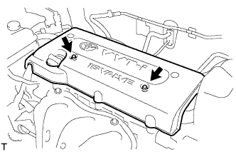
| 6. REMOVE NO. 1 ENGINE COVER |
Remove the 2 nuts and cover.
 |
| 7. DRAIN ENGINE OIL |
Remove the oil filler cap.
Remove the oil drain plug and drain the oil into a container.
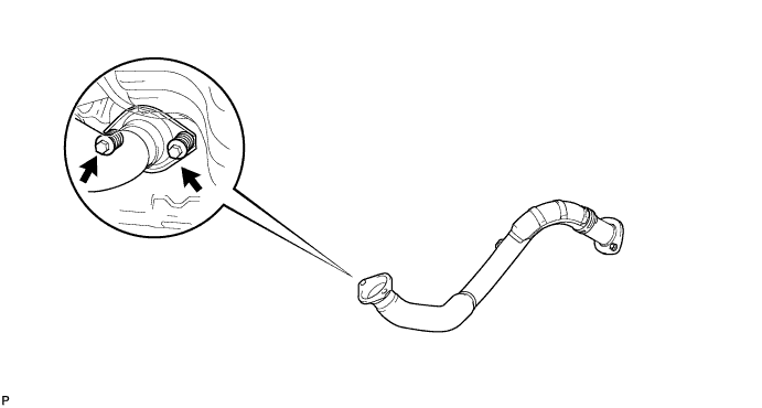
| 8. REMOVE FRONT EXHAUST PIPE |
Remove the 2 bolts, 2 compression springs and front exhaust pipe.
Remove the gasket from the exhaust manifold.
| 9. REMOVE FRONT SUSPENSION MEMBER REINFORCEMENT RH |
Remove the 4 bolts and reinforcement RH.
| 10. REMOVE FAN AND GENERATOR V BELT |
Using SST 19 mm socket wrench, loosen the V-ribbed belt tensioner arm clockwise, then remove the fan and generator V belt.
- SST
- 09216-42010
- NOTICE:
- Be sure to connect SST and the tools so that they are in line during use.
- When retracting the tensioner, turn it clockwise slowly for 3 seconds or more. Do not apply force rapidly.
- After the tensioner is fully retracted, do not apply force any more than necessary.
 |
| 11. REMOVE GENERATOR ASSEMBLY |
Disconnect the generator connector.
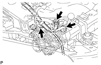 |
Remove the terminal cap.
Remove the nut and disconnect the generator wire.
Remove the bolt and wire harness clamp bracket.
Remove the wire harness clamp.
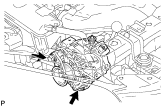
Remove the 2 bolts and generator.
 |
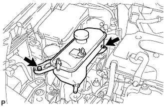
| 12. REMOVE RADIATOR RESERVOIR TANK |
Remove the 2 bolts and radiator reservoir.
 |
| 13. REMOVE ENGINE MOUNTING INSULATOR FR |
Place a transmission jack underneath the engine, then put a wooden block on the jack.
 |
Remove the through bolt and nut.
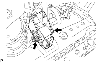 |
Remove the 2 bolts and engine mounting insulator FR.
- HINT:
- Keep clearance by lowering the engine using the transmission jack when removing the engine mounting insulator FR.
 |
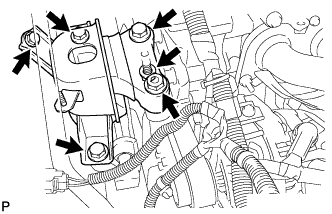
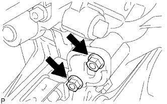
| 14. REMOVE ENGINE MOUNTING INSULATOR RH |
Remove the 4 bolts, 2 nuts and engine mounting insulator RH.
- NOTICE:
- Do not apply excessive force to the return tube when removing the engine mounting insulator RH.
- HINT:
- Keep clearance by lowering the engine using the transmission jack when removing the engine mounting insulator RH.
 |
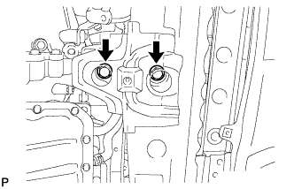
| 15. REMOVE IDLER PULLEY BRACKET |
Loosen the 2 bolts and remove the bracket together with the 2 bolts.
 |
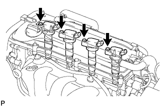
| 16. REMOVE IGNITION COIL ASSEMBLY |
Disconnect the 4 ignition coil connectors.
Remove the 4 bolts and 4 ignition coils.
 |
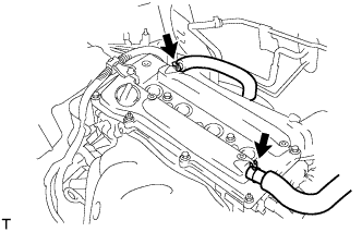
| 17. REMOVE CYLINDER HEAD COVER SUB-ASSEMBLY |
Disconnect the 2 ventilation hoses from the cylinder head cover.
 |
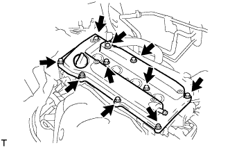
Remove the 2 bolts and disconnect the 2 engine wires.
 |
Remove the 8 bolts, 2 nuts and cylinder head cover.
 |
| 18. REMOVE OIL PAN SUB-ASSEMBLY |
Install the No. 1 and No. 2 engine hangers with the bolts.
- Torque:
- 38 N*m{387 kgf*cm, 28 ft.*lbf}
Part No. Item Part No. No. 1 engine hanger 12281-28010 No. 2 engine hanger 12282-28010 Bolt 91512-61020
 |
Attach the sling device to the engine hangers and chain block.
Remove the 12 bolts and 2 nuts.
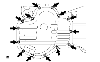 |
Insert the blade of an oil pan seal cutter between the crankcase, chain cover and oil pan and cut off the applied sealer and remove the oil pan.
- NOTICE:
- Be careful not to damage the contact surface of the crankcase, chain cover and oil pan.
 |
| 19. SET NO. 1 CYLINDER TO TDC/COMPRESSION |
Turn the crankshaft pulley until its groove and the timing mark "0" of the timing chain cover are aligned.
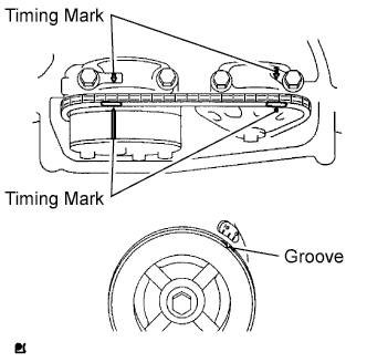 |
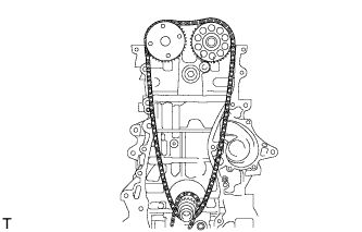
Check that each timing mark of the camshaft timing gear and sprocket is aligned with each timing mark located on the No. 1 and No. 2 bearing caps as shown in the illustration.
If not, turn the crankshaft by 1 revolution (360°) to align the timing marks as above.
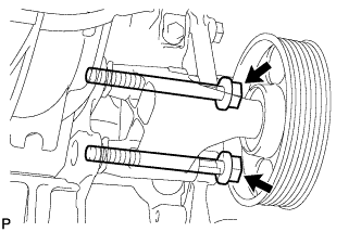
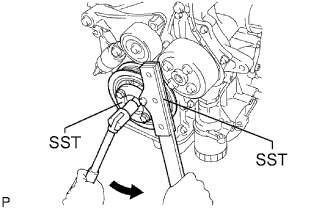
| 20. REMOVE CRANKSHAFT PULLEY |
Using SST, fix the pulley in place and loosen the pulley bolt.
- SST
- 09213-54015(91651-60855)
09330-00021
 |
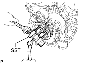
Remove the crankshaft pulley.
- HINT:
- If necessary, remove the pulley and pulley bolt using SST.
- SST
- 09950-50013(09951-05010,09952-05010,09953-05020,09954-05021)
09950-40011(09957-04010)
 |
| 21. REMOVE NO. 1 CHAIN TENSIONER ASSEMBLY |
Remove the 2 nuts, chain tensioner and gasket.
- NOTICE:
- Do not turn the crankshaft without the chain tensioner.
 |
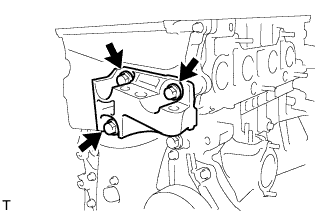
| 22. REMOVE ENGINE MOUNTING BRACKET RH |
Remove the 3 bolts and engine mounting bracket RH.
 |
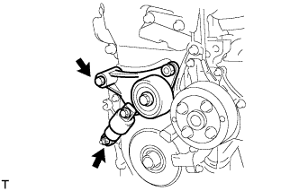
| 23. REMOVE V-RIBBED BELT TENSIONER ASSEMBLY |
Lift the engine upward using the transmission jack.
- NOTICE:
- Do not lift the engine more than necessary.
Remove the bolt, nut and V-ribbed belt tensioner.
 |
| 24. REMOVE CRANKSHAFT POSITION SENSOR |
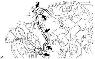 |
Disconnect the sensor connector.
Remove the connector clamp.
Remove the wire harness from the wire harness clamp bracket.
Remove the wire harness clamp.
Remove the bolt and sensor.
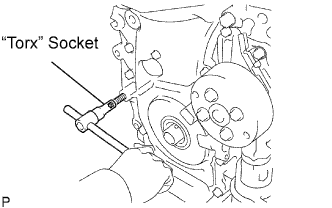
| 25. REMOVE TIMING CHAIN COVER SUB-ASSEMBLY |
Using an E10 "torx" socket, remove the stud bolt for the V-ribbed belt tensioner.
 |
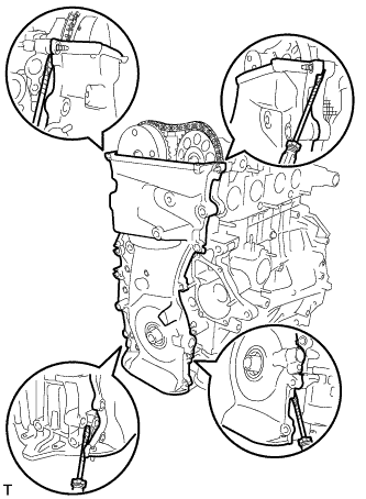
Remove the 11 bolts and 2 nuts.
 |
Remove the timing chain cover by prying the portions between the timing chain cover, cylinder head and cylinder block with a screwdriver.
- NOTICE:
- Be careful not to damage the contact surfaces of the timing chain cover, cylinder head and cylinder block.
 |
| 26. REMOVE NO. 1 CRANKSHAFT POSITION SENSOR PLATE |
 |
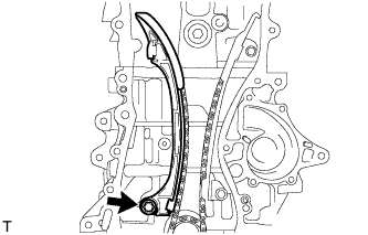
| 27. REMOVE TIMING CHAIN GUIDE |
Remove the bolt and timing chain guide.
 |
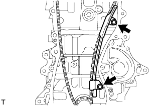
| 28. REMOVE CHAIN TENSIONER SLIPPER |
Remove the bolt and chain tensioner slipper.
 |
| 29. REMOVE NO. 1 CHAIN VIBRATION DAMPER |
Remove the 2 bolts and chain vibration damper.
 |
| 30. REMOVE CHAIN SUB-ASSEMBLY |
 |
| 31. REMOVE CRANKSHAFT TIMING SPROCKET |
 |
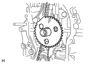
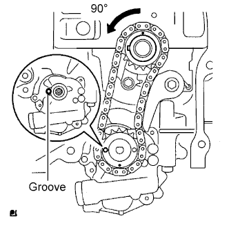
| 32. REMOVE NO. 2 CHAIN SUB-ASSEMBLY |
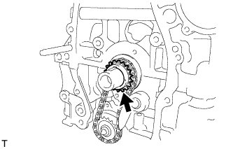
Turn the crankshaft by 90° counterclockwise to align the adjusting hole of the oil pump drive shaft sprocket with the groove of the oil pump.
 |
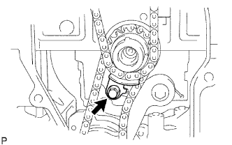
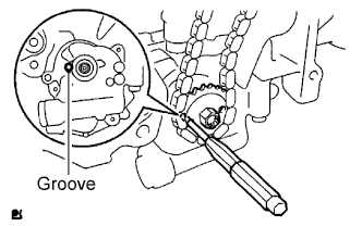
Insert a 4 mm diameter bar into the adjusting hole of the oil pump drive shaft sprocket to lock the gear in position, and then remove the nut.
 |
Remove the bolt, chain tensioner plate and spring.
 |
Remove the oil pump drive sprocket, oil pump drive shaft sprocket and No. 2 chain.