Lighting System Back-Up Light Circuit
Lighting. Toyota Rav4. Aca30, 33, 38 Gsa33 Zsa30, 35
DESCRIPTION
WIRING DIAGRAM
INSPECTION PROCEDURE
INSPECT FUSE (GAUGE1)
INSPECT BULB (BACK-UP LIGHT BULB)
CHECK TRANSAXLE TYPE
INSPECT PARK / NEUTRAL POSITION SWITCH
CHECK WIRE HARNESS (PARK/NEUTRAL POSITION SWITCH - BATTERY)
CHECK WIRE HARNESS (SWITCH - REAR COMBINATION LIGHT)
INSPECT BACK-UP LIGHT SWITCH
CHECK WIRE HARNESS (BACK-UP LIGHT SWITCH - BATTERY)
CHECK WIRE HARNESS (BACK-UP LIGHT SWITCH - REAR COMBINATION LIGHT)
LIGHTING SYSTEM - Back-up Light Circuit |
DESCRIPTION
A/T models: The park/neutral position switch turns on when the shift lever is moved into the R position, causing the back-up light to illuminate.M/T models: The back-up light switch turns on when the shift lever is moved into the R position, causing the back-up light to illuminate.
WIRING DIAGRAM
INSPECTION PROCEDURE
Remove the GAUGE1 fuse from the instrument panel junction block.
Measure the resistance of the fuse.
- Standard resistance:
- Below 1 Ω
| 2.INSPECT BULB (BACK-UP LIGHT BULB) |
Remove the rear combination light assembly.
Connect the positive (+) lead from the battery to terminal 6 and the negative (-) lead to terminal 1, then check that the bulb illuminates.
- OK:
- Bulb illuminates.
- Result:
Transaxle Type
| Proceed to
|
A/T
| A
|
M/T
| B
|
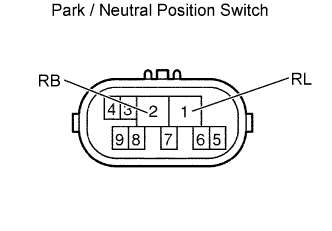
| 4.INSPECT PARK / NEUTRAL POSITION SWITCH |
Disconnect the B28 park / neutral position switch connector.
Measure the resistance of the switch.
- Standard resistance:
Tester Condition
| Shift Position
| Specified Condition
|
2 (RB) - 1 (RL)
| R
| Below 1 Ω
|
2 (RB) - 1 (RL)
| Except R
| 10 kΩ or higher
|
| | REPLACE PARK/NEUTRAL POSITION SWITCH |
|
|
| 5.CHECK WIRE HARNESS (PARK/NEUTRAL POSITION SWITCH - BATTERY) |
Disconnect the B28 park / neutral position switch connector.
Measure the voltage of the wire harness side connector.
- Standard voltage:
Tester Condition
| Condition
| Specified Condition
|
B28-2 (RB) - Body ground
| Ignition switch on (IG)
| 10 to 14 V
|
| | REPAIR OR REPLACE HARNESS AND CONNECTOR |
|
|
| 6.CHECK WIRE HARNESS (SWITCH - REAR COMBINATION LIGHT) |
Disconnect the B28 park/neutral position switch connector.
Disconnect the K13 or K15 rear combination light connector.
Measure the resistance of the wire harness side connectors.
- Standard resistance:
Tester Condition
| Specified Condition
|
B28-1 - K13-1
| Below 1 Ω
|
B28-1 - K15-1
| Below 1 Ω
|
| | REPAIR OR REPLACE HARNESS AND CONNECTOR |
|
|
| OK |
|
|
|
| REPAIR OR REPLACE HARNESS AND CONNECTOR (REAR COMBINATION LIGHT - BODY GROUND) |
|
| 7.INSPECT BACK-UP LIGHT SWITCH |
Disconnect the B25 back-up light switch connector.
Measure the resistance of the switch.
- Standard resistance:
Tester Condition
| Shift Position
| Specified Condition
|
2 - 1
| R (Pushed)
| Below 1 Ω
|
2 - 1
| Except R (Not pushed)
| 10 kΩ or higher
|
| | REPLACE BACK-UP LIGHT SWITCH |
|
|
| 8.CHECK WIRE HARNESS (BACK-UP LIGHT SWITCH - BATTERY) |
Disconnect the B25 back-up light switch connector.
Measure the voltage of the wire harness side connector.
- Standard voltage:
Tester Condition
| Condition
| Specified Condition
|
B25-2 - Body ground
| Ignition switch on (IG)
| 10 to 14 V
|
| | REPAIR OR REPLACE HARNESS AND CONNECTOR |
|
|
| 9.CHECK WIRE HARNESS (BACK-UP LIGHT SWITCH - REAR COMBINATION LIGHT) |
Disconnect the B25 back-up light switch connector.
Disconnect the K13 and K15 rear combination light connectors.
Measure the resistance of the wire harness side connectors.
- Standard resistance:
Tester Condition
| Specified Condition
|
B25-1 - K13-1
| Below 1 Ω
|
B25-1 - K15-1
| Below 1 Ω
|
| | REPAIR OR REPLACE HARNESS AND CONNECTOR |
|
|
| OK |
|
|
|
| REPAIR OR REPLACE HARNESS AND CONNECTOR (REAR COMBINATION LIGHT - BODY GROUND) |
|