Lighting. Toyota Rav4. Aca30, 33, 38 Gsa33 Zsa30, 35
DESCRIPTION
WIRING DIAGRAM
INSPECTION PROCEDURE
CHECK VEHICLE EQUIPMENT
INSPECT FUSE (STOP)
INSPECT STOP LIGHT SWITCH
CHECK WIRE HARNESS (STOP LIGHT SWITCH - BATTERY)
CHECK STOP LIGHT CONTROL RELAY
INSPECT STOP LIGHT (REAR COMBINATION LIGHT)
INSPECT REAR STOP LIGHT (HIGH MOUNT STOP LIGHT)
INSPECT BRK RELAY
CHECK WIRE HARNESS (STOP LIGHT CONTROL RELAY - REAR STOP LIGHT)
CHECK WIRE HARNESS (STOP LIGHT CONTROL RELAY - BATTERY AND BODY GROUND)
CHECK WIRE HARNESS (STOP LIGHT SWITCH - STOP LIGHT CONTROL RELAY)
REPLACE FUSE (STOP)
INSPECT STOP LIGHT (REAR COMBINATION LIGHT)
INSPECT STOP LIGHT (HIGH MOUNT STOP LIGHT)
INSPECT BRK RELAY
INSPECT STOP LIGHT SWITCH
CHECK WIRE HARNESS (STOP LIGHT SWITCH - BATTERY)
CHECK WIRE HARNESS (STOP LIGHT SWITCH - REAR STOP LIGHT)
LIGHTING SYSTEM - Stop Light Switch Circuit |
DESCRIPTION
When the stop light switch is turned on, current flows to the stop lights to illuminate them.
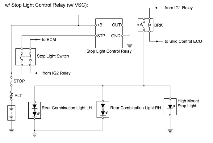
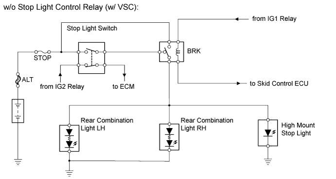
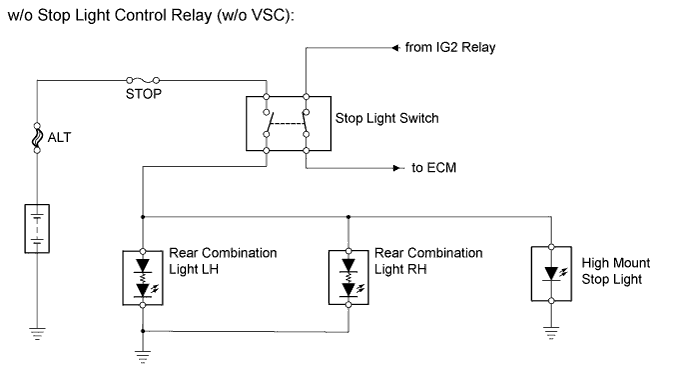
WIRING DIAGRAM
INSPECTION PROCEDURE
| 1.CHECK VEHICLE EQUIPMENT |
Check if the stop light control relay is equipped on the vehicle.
ResultResult
| Proceed to
|
w/ stop light control relay
| A
|
w/o stop light control relay
| B
|
Remove the STOP fuse from the instrument panel junction block.
Measure the resistance of the fuse.
- Standard resistance:
- Below 1 Ω
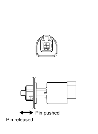
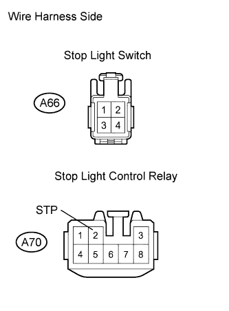
| 3.INSPECT STOP LIGHT SWITCH |
Remove the stop light switch.
Measure the resistance of the switch.
- Standard resistance:
Tester Connection
| Switch Condition
| Specified Condition
|
1 - 2
| Pin pushed
| 10 kΩ higher
|
Pin released
| Below 1 Ω
|
3 - 4
| Pin pushed
| Below 1 Ω
|
Pin released
| 10 kΩ higher
|
| | REPLACE STOP LIGHT SWITCH |
|
|
| 4.CHECK WIRE HARNESS (STOP LIGHT SWITCH - BATTERY) |
Disconnect the A66 stop light switch connector.
Measure the voltage of the wire harness side connector.
- Standard voltage:
Tester Connection
| Specified Condition
|
A66-2 - Body ground
| 11 to 14 V
|
| | REPAIR OR REPLACE HARNESS AND CONNECTOR |
|
|
| 5.CHECK STOP LIGHT CONTROL RELAY |
Measure the voltage of the stop light control relay.
- Standard voltage:
Tester Connection
| Condition
| Specified Condition
|
A70-8 (OUT) - Body ground
| Brake pedal released
| Below 1 V
|
Brake pedal depressed
| 11 to 14 V
|
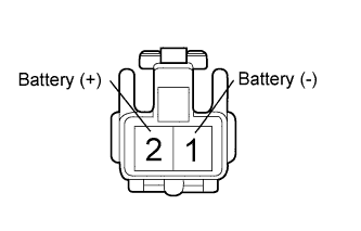
| 6.INSPECT STOP LIGHT (REAR COMBINATION LIGHT) |
Remove the rear combination light.
Connect the positive (+) lead from the battery to terminal 4 and the negative (-) lead to terminal 1, then check that the light comes on.
- OK:
- Light comes on.
| | REPLACE REAR COMBINATION LIGHT |
|
|
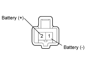
| 7.INSPECT REAR STOP LIGHT (HIGH MOUNT STOP LIGHT) |
Remove the high mount stop light assembly.
Connect the positive (+) lead from the battery to terminal 2 and the negative (-) lead to terminal 1, then check that the light comes on.
- OK:
- Light comes on
ResultResult
| Proceed to
|
OK (w/ VSC)
| A
|
OK (w/o VSC)
| B
|
NG
| C
|
| |
|
| | REPLACE HIGH MOUNT STOP LIGHT ASSEMBLY |
|
|
Remove the BRK relay from the engine room No. 1 relay block.
Measure the resistance of the relay.
- Standard resistance:
Tester Connection
| Specified Condition
|
3 - 4
| Below 1 Ω
|
3 - 4
| 10 kΩ or higher
(Battery voltage applied to terminals 1 and 2)
|
3 - 5
| 10 kΩ or higher
|
3 - 5
| Below 1 Ω
(Battery voltage applied to terminals 1 and 2)
|
| 9.CHECK WIRE HARNESS (STOP LIGHT CONTROL RELAY - REAR STOP LIGHT) |
Disconnect the A70 stop light control relay connector.
Disconnect the K13 (for RH) and K15 (for LH) rear combination light connectors.
Disconnect the S1 high mount stop light connector.
Measure the resistance of the wire harness side connectors.
- Standard resistance:
Tester Connection
| Specified Condition
|
A70-8 (OUT) - K13-4
| Below 1 Ω
|
A70-8 (OUT) or K13-4 - Body ground
| 10 kΩ or higher
|
A70-8 (OUT) - K15-4
| Below 1 Ω
|
A70-8 (OUT) or K15-4 - Body ground
| 10 kΩ or higher
|
A70-8 (OUT) - S1-2
| Below 1 Ω
|
A70-8 (OUT) or S1-2 - Body ground
| 10 kΩ or higher
|
| | REPAIR OR REPLACE HARNESS AND CONNECTOR |
|
|
| OK |
|
|
|
| REPAIR OR REPLACE HARNESS AND CONNECTOR (REAR STOP LIGHT - BODY GROUND) |
|
| 10.CHECK WIRE HARNESS (STOP LIGHT CONTROL RELAY - BATTERY AND BODY GROUND) |
Disconnect the A70 stop light control relay connector.
Measure the resistance of the wire harness side connector.
- Standard voltage:
Tester Connection
| Condition
| Specified Condition
|
A70-6 (+B) - Body ground
| Always
| 11 to 14 V
|
Measure the resistance of the wire harness side connector.
- Standard resistance:
Tester Connection
| Condition
| Specified Condition
|
A70-4 (GND) - Body ground
| Always
| Below 1 Ω
|
| | REPAIR OR REPLACE HARNESS AND CONNECTOR |
|
|
| 11.CHECK WIRE HARNESS (STOP LIGHT SWITCH - STOP LIGHT CONTROL RELAY) |
Disconnect the A66 stop light switch connector.
Disconnect the A70 stop light control relay connector.
Measure the resistance of the wire harness side connectors.
- Standard resistance:
Tester Connection
| Specified Condition
|
A66-1 - A70-2 (STP)
| Below 1 Ω
|
A66-1 or A70-2 (STP) - Body ground
| 10 kΩ or higher
|
| | REPAIR OR REPLACE HARNESS AND CONNECTOR |
|
|
| OK |
|
|
|
| REPLACE STOP LIGHT CONTROL RELAY |
|
Remove the STOP fuse from the instrument panel junction block.
Measure the resistance of the fuse.
- Standard resistance:
- Below 1 Ω
| 13.INSPECT STOP LIGHT (REAR COMBINATION LIGHT) |
Remove the rear combination light.
Connect the positive (+) lead from the battery to terminal 4 and the negative (-) lead to terminal 1, then check that the light comes on.
- OK:
- Light comes on.
| | REPLACE REAR COMBINATION LIGHT |
|
|
| 14.INSPECT STOP LIGHT (HIGH MOUNT STOP LIGHT) |
Remove the high mount stop light.
Connect the positive (+) lead from the battery to terminal 2 and the negative (-) lead to terminal 1, then check that the light comes on.
- OK:
- Light comes on
ResultResult
| Proceed to
|
OK: w/ VSC
| A
|
OK: w/o VSC
| B
|
NG
| C
|
| |
|
| | REPLACE HIGH MOUNT STOP LIGHT ASSEMBLY |
|
|
Remove the BRK relay from the engine room No. 1 relay block.
Measure the resistance of the relay.
- Standard resistance:
Tester Connection
| Specified Condition
|
3 - 4
| Below 1 Ω
|
3 - 4
| 10 kΩ or higher
(Battery voltage applied to terminals 1 and 2)
|
3 - 5
| 10 kΩ or higher
|
3 - 5
| Below 1 Ω
(Battery voltage applied to terminals 1 and 2)
|
| 16.INSPECT STOP LIGHT SWITCH |
Remove the stop light switch.
Measure the resistance of the switch.
- Standard resistance:
Tester Connection
| Switch Condition
| Specified Condition
|
1 - 2
| Pin pushed
| 10 kΩ higher
|
Pin released
| Below 1 Ω
|
3 - 4
| Pin pushed
| Below 1 Ω
|
Pin released
| 10 kΩ higher
|
| | REPLACE STOP LIGHT SWITCH |
|
|
| 17.CHECK WIRE HARNESS (STOP LIGHT SWITCH - BATTERY) |
Disconnect the A5 stop light switch connector.
Measure the voltage of the wire harness side connector.
- Standard voltage:
Tester Connection
| Specified Condition
|
A5-2 - Body ground
| 11 to 14 V
|
| | REPAIR OR REPLACE HARNESS AND CONNECTOR |
|
|
| 18.CHECK WIRE HARNESS (STOP LIGHT SWITCH - REAR STOP LIGHT) |
Disconnect the A5 stop light switch connector.
Disconnect the K13 and K15 rear combination light connectors.
Disconnect the S1 high mount stop light connector.
Measure the resistance of the wire harness side connectors.
- Standard resistance:
Tester Connection
| Specified Condition
|
A5-1 - K13-4
| Below 1 Ω
|
A5-1 or K13-4 - Body ground
| 10 kΩ or higher
|
A5-1 - K15-4
| Below 1 Ω
|
A5-1 or K15-4 - Body ground
| 10 kΩ or higher
|
A5-1 - S1-2
| Below 1 Ω
|
A5-1 or S1-2 - Body ground
| 10 kΩ or higher
|
| | REPAIR OR REPLACE HARNESS AND CONNECTOR |
|
|
| OK |
|
|
|
| REPAIR OR REPLACE HARNESS AND CONNECTOR (REAR STOP LIGHT - BODY GROUND) |
|