INSTALL PARKING BRAKE SHOE RETURN TENSION SPRING (for Lower Side)
INSTALL PARKING BRAKE SHOE RETURN TENSION SPRING (for Upper Side)
Parking Brake Assembly -- Reassembly |
- HINT:
- Use the same procedures for the RH side and LH side.
- The procedures listed below are for the LH side.
| 1. APPLY HIGH TEMPERATURE GREASE |
Apply high temperature grease to the contact surface of the shoe and backing plate.
| 2. INSTALL PARKING BRAKE SHOE LEVER LH |
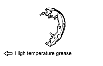
| 3. INSTALL NO. 2 PARKING BRAKE SHOE ASSEMBLY LH |
Connect the parking brake cable to the parking brake shoe lever.
Apply high temperature grease to the following contact surfaces of the shoe.
- Shoe to anchor pin
- Shoe to parking brake lever pin
- Shoe to spring
- Shoe to anchor pin
 |
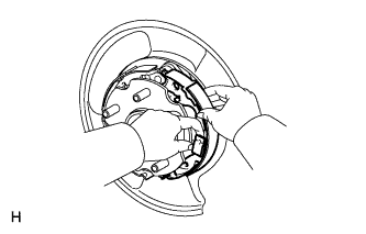
Install the shoe with the shoe hold-down spring and pin.
 |
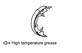
| 4. INSTALL NO. 1 PARKING BRAKE SHOE ASSEMBLY LH |
Apply high temperature grease to the following contact surfaces of the shoe.
- Shoe to anchor pin
- Shoe to spring
- Shoe to anchor pin
 |
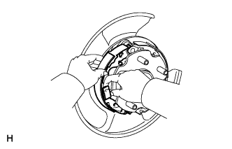
Install the shoe with the shoe hold-down spring and pin.
 |
| 5. INSTALL PARKING BRAKE SHOE ADJUSTING SCREW SET |
Apply high temperature grease to the areas of the shoe adjusting screw set shown in the illustration.
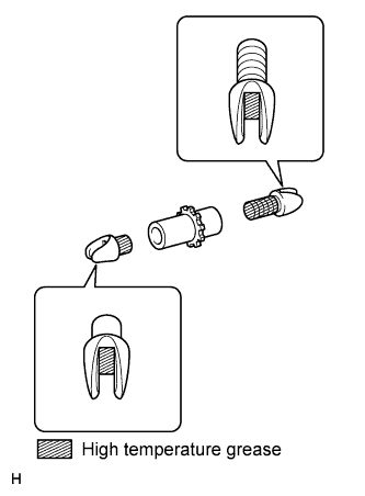 |
Install the screw set.
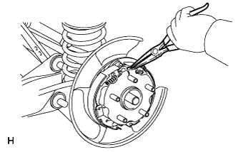
| 6. INSTALL PARKING BRAKE SHOE RETURN TENSION SPRING (for Lower Side) |
Using needle-nose pliers, install the tension spring.
| 7. INSTALL PARKING BRAKE SHOE STRUT LH |
Apply high temperature grease to the contact surface of the strut and shoe return tension spring.
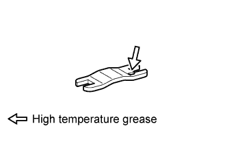 |
Install the strut.
| 8. INSTALL PARKING BRAKE SHOE RETURN TENSION SPRING (for Upper Side) |
Using needle-nose pliers, install the 2 shoe return tension springs.
 |
| 9. CHECK PARKING BRAKE INSTALLATION |
Check that each part is installed properly.
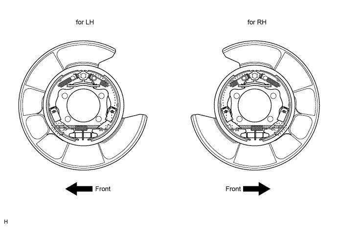
- NOTICE:
- There should be no oil or grease adhering to the friction surfaces of the shoe lining and disc.
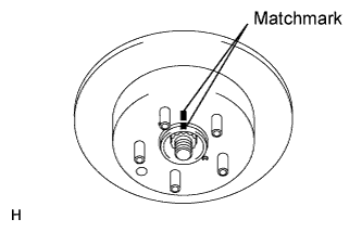
| 10. INSTALL REAR DISC |
Align the matchmarks and install the disc.
- HINT:
- When replacing the disc with a new one, select the installation position where the disc has the smallest runout.
 |
| 11. ADJUST PARKING BRAKE SHOE CLEARANCE |
Temporarily install the hub nuts.
Remove the shoe adjusting hole plug, and then turn the adjuster to expand the shoe adjuster until the disc locks.
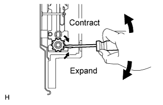 |
Turn the shoe adjuster so that it contracts to a point where the disc can rotate smoothly.
- Standard:
- 8 notches
Check that the shoe has no brake drag.
| 12. INSTALL PARKING BRAKE SHOE ADJUSTING HOLE PLUG |
Install the shoe adjusting hole plug to the rear disc.
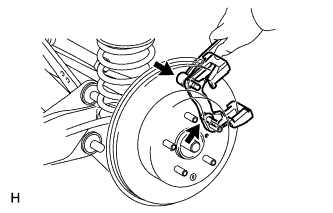
| 13. CONNECT REAR DISC BRAKE CYLINDER MOUNTING LH |
Install the cylinder mounting with the 2 bolts.
- Torque:
- 88 N*m{897 kgf*cm, 65 ft.*lbf}
 |
| 14. INSTALL REAR WHEEL |
- Torque:
- 103 N*m{1050 kgf*cm, 76 ft.*lbf}
| 15. SETTLE PARKING BRAKE SHOE AND DISC |
Pull the parking brake lever with a force of 147 N (15 kgf, 33 lbf).
Drive the vehicle at approximately 50 km/h (31 mph) for approximately 400 m (0.25 miles).
- NOTICE:
- Drive the vehicle on a safe, level and dry road.
Repeat the above steps 2 or 3 times.
| 16. CHECK PARKING BRAKE LEVER TRAVEL |
Pull the lever upward with a force of approximately 200 N (20 kgf, 44 lbf) and count the number of clicks.
- OK:
- 6 to 8 clicks (without rear brake dragging)
| 17. ADJUST PARKING BRAKE LEVER TRAVEL |
Turn the No. 1 wire adjusting nut until the lever travel is correct.
- OK:
- 6 to 8 clicks (without rear brake dragging)
<Lever pulling force: approximately 200 N (20 kgf, 44 lbf)>
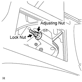 |
Tighten the lock nut.
- Torque:
- 6.0 N*m{61 kgf*cm, 53 in.*lbf}
Operate the parking brake lever 3 to 4 times, and check the parking brake lever travel.
- OK:
- 6 to 8 clicks (without rear brake dragging)
<Lever pulling force: approximately 200 N (20 kgf, 44 lbf)>
When operating the parking brake lever, check that the brake warning light illuminates at the first click.
- Standard condition:
- Brake warning light always illuminates at the first click.