DESCRIPTION
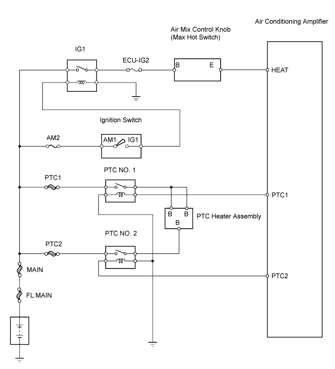
WIRING DIAGRAM
INSPECTION PROCEDURE
INSPECT FUSE (PTC1, PTC2)
INSPECT AIR MIX CONTROL KNOB (MAX HOT SWITCH)
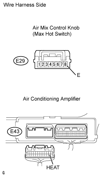
CHECK WIRE HARNESS (AIR MIX CONTROL KNOB - BATTERY)
CHECK WIRE HARNESS (AIR MIX CONTROL KNOB - AIR CONDITIONING AMPLIFIER)
INSPECT PTC HEATER RELAY (Marking: PTC NO. 1, PTC NO. 2)
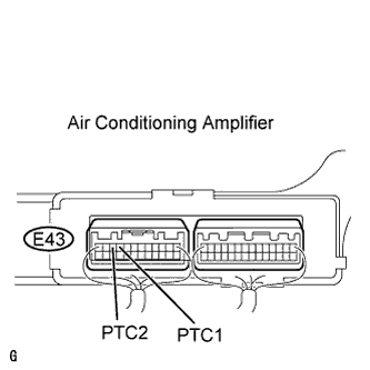
CHECK AIR CONDITIONING AMPLIFIER
CHECK WIRE HARNESS (AIR CONDITIONING AMPLIFIER - PTC HEATER RELAY)
CHECK WIRE HARNESS (PTC HEATER RELAY - BODY GROUND)
CHECK WIRE HARNESS (PTC HEATER - PTC HEATER RELAY)
CHECK WIRE HARNESS (BATTERY - PTC HEATER RELAY)
CHECK PTC HEATER
AIR CONDITIONING SYSTEM (for Manual Air Conditioning System) - PTC Heater Circuit |
DESCRIPTION
PTC heater relays are closed in accordance with signals from the air conditioning amplifier and power is supplied to the PTC heater assembly installed on the radiator heater unit.
WIRING DIAGRAM
INSPECTION PROCEDURE
| 1.INSPECT FUSE (PTC1, PTC2) |
Remove the PTC1 and PTC2 H-fuses from the engine room No. 2 relay block.
Measure the resistance of the H-fuses.
- Standard resistance:
- Below 1 Ω
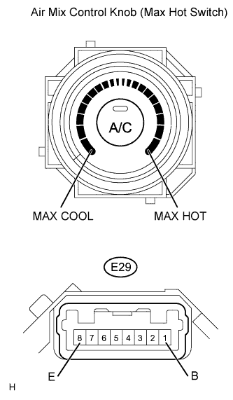
| 2.INSPECT AIR MIX CONTROL KNOB (MAX HOT SWITCH) |
Remove the air mix control knob.
Measure the resistance of the knob.
- Standard resistance:
Tester Connection
| Condition
| Specified Condition
|
E29-2 (B) - E29-8 (E)
| Max hot position
| Below 1 Ω
|
E29-2 (B) - E29-8 (E)
| Other than max hot position
| 10 kΩ or higher
|
| | REPLACE AIR MIX CONTROL KNOB |
|
|
| 3.CHECK WIRE HARNESS (AIR MIX CONTROL KNOB - BATTERY) |
Disconnect the E29 control knob connector.
Measure the voltage of the wire harness side connector.
- Standard voltage:
Tester Connection
| Condition
| Specified Condition
|
E29-2 (B) - Body ground
| Ignition switch on (IG)
| 10 to 14 V
|
| | REPAIR OR REPLACE HARNESS AND CONNECTOR |
|
|
| 4.CHECK WIRE HARNESS (AIR MIX CONTROL KNOB - AIR CONDITIONING AMPLIFIER) |
Disconnect the E29 control knob connector.
Disconnect the E43 amplifier connector.
Measure the resistance of the wire harness side connectors.
- Standard resistance:
Tester Connection
| Specified Condition
|
E29-8 (E) - E43-14 (HEAT)
| Below 1 Ω
|
| | REPAIR OR REPLACE HARNESS AND CONNECTOR |
|
|
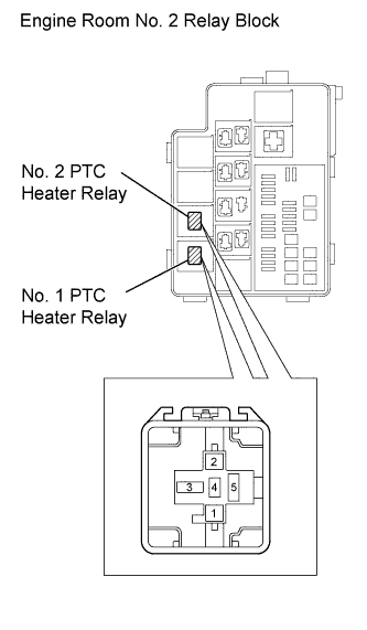
| 5.INSPECT PTC HEATER RELAY (Marking: PTC NO. 1, PTC NO. 2) |
Remove the No. 1 and No. 2 PTC heater relays from the engine room No. 2 relay block.
Measure the resistance of the relays.
- Standard resistance:
Tester Connection
| Specified Condition
|
3 - 5
| 10 kΩ or higher
|
3 - 5
| Below 1 Ω
(when battery voltage is applied to terminals 1 and 2)
|
| 6.CHECK AIR CONDITIONING AMPLIFIER |
Remove the air conditioning amplifier with its connectors still connected.
Turn the ignition switch on (IG).
When the PTC heater operating conditions are met (engine at idle speed or faster, ambient temperature is 10°C (50°F) or less, engine coolant temperature is 65°C (149°F) or less, air mix control knob setting is MAX HOT), turn the blower switch to the Lo setting.
Measure the voltage of the wire harness side connectors.
- Standard voltage:
Tester Connection
| Specified Condition
|
E43-9 (PTC1) - Body ground
| 10 to 14 V
|
E43-10 (PTC2) - Body ground
| 10 to 14 V
|
| 7.CHECK WIRE HARNESS (AIR CONDITIONING AMPLIFIER - PTC HEATER RELAY) |
Remove the No. 1 and No. 2 PTC heater relays from the engine room No. 2 relay block.
Turn the ignition switch on (IG).
When the PTC heater operating conditions are met (engine at idle speed or faster, ambient temperature is 10°C (50°F) or less, engine coolant temperature is 65°C (149°F) or less, air mix control knob setting is MAX HOT), turn the blower switch to the Lo setting.
Measure the voltage of the wire harness side connectors
- Standard voltage:
Tester Connection
| Specified Condition
|
No. 1 PTC heater relay terminal 1 - Body ground
| 10 to 14 V
|
No. 2 PTC heater relay terminal 2 - Body ground
| 10 to 14 V
|
| | REPAIR OR REPLACE HARNESS AND CONNECTOR |
|
|
| 8.CHECK WIRE HARNESS (PTC HEATER RELAY - BODY GROUND) |
Remove the No. 1 and No. 2 PTC heater relays from the engine room No. 2 relay block.
Measure the resistance of the wire harness side connectors.
- Standard resistance:
Tester Connection
| Specified Condition
|
No. 1 PTC heater relay terminal 2 - Body ground
| Below 1 Ω
|
No. 2 PTC heater relay terminal 1 - Body ground
| Below 1 Ω
|
| | REPAIR OR REPLACE HARNESS AND CONNECTOR |
|
|
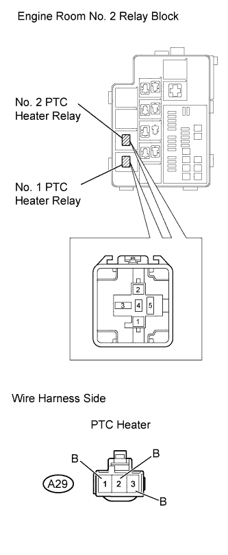
| 9.CHECK WIRE HARNESS (PTC HEATER - PTC HEATER RELAY) |
Remove the No. 1 and No. 2 PTC heater relays from the engine room No. 2 relay block.
Measure the resistance of the wire harness side connectors.
- Standard resistance:
Tester Connection
| Specified Condition
|
No. 1 PTC heater relay terminal 3 - A29-3 (B)
| Below 1 Ω
|
No. 2 PTC heater relay terminal 3 - A29-2 (B)
| Below 1 Ω
|
No. 1 PTC heater relay terminal 3 - A29-1 (B)
| Below 1 Ω
|
| | REPAIR OR REPLACE HARNESS AND CONNECTOR |
|
|
| 10.CHECK WIRE HARNESS (BATTERY - PTC HEATER RELAY) |
Remove the No. 1 and No. 2 PTC heater relays from the engine room No. 2 relay block.
Measure the voltage of the wire harness side connectors.
- Standard voltage:
Tester Connection
| Specified Condition
|
No. 1 PTC heater relay terminal 5 - Body ground
| 10 to 14 V
|
No. 2 PTC heater relay terminal 5 - Body ground
| 10 to 14 V
|
| | REPAIR OR REPLACE HARNESS AND CONNECTOR |
|
|
After replacing the PTC heater with a normal one, check that the PTC heater function operates normally.
- OK:
- PTC heater function operates normally.
| NG |
|
|
|
| PROCEED TO NEXT CIRCUIT INSPECTION SHOWN IN PROBLEM SYMPTOMS TABLE |
|