Fuel Injector -- Removal |
| 1. DISCHARGE FUEL SYSTEM PRESSURE |
Discharge fuel system pressure (RAV4_ACA30 RM000001EEY01OX.html).
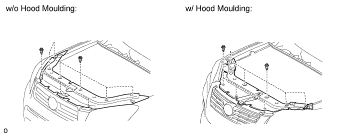
| 2. REMOVE RADIATOR SUPPORT OPENING COVER |
Remove the 9 clips and radiator support opening cover.
| 3. DISCONNECT CABLE FROM NEGATIVE BATTERY TERMINAL |
- NOTICE:
- w/ Navigation System (for HDD):
- After the ignition switch is turned off, the HDD navigation system requires approximately a minute to record various types of memory and settings. As a result, after turning the ignition switch off, wait a minute or more before disconnecting the cable from the negative (-) battery terminal.
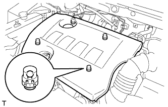
| 4. REMOVE NO. 2 CYLINDER HEAD COVER |
Hold the rear of the cover and raise it to detach the 2 clips on the rear of the cover. Continue to raise the cover to detach the 2 clips on the front of the cover and remove the cover.
- NOTICE:
- Attempting to detach both front and rear clips at the same time may cause the cover to break.
 |
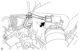
| 5. REMOVE AIR CLEANER CAP SUB-ASSEMBLY |
Disconnect the mass air flow meter connector.
 |
Detach the clamp.
Disconnect the No. 2 ventilation hose from the cylinder head cover.
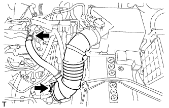 |
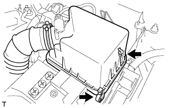
Squeeze the taps of the air cleaner hose clamp, and then disconnect the air cleaner hose from the throttle body.
Detach the 2 hook clamps, and then remove the air cleaner cap and hose.
 |
| 6. REMOVE AIR CLEANER CASE SUB-ASSEMBLY |
Disconnect the wire harness clamp from the air cleaner case.
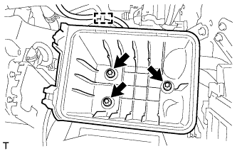 |
Remove the 3 bolts and air cleaner case.
| 7. REMOVE BATTERY CLAMP SUB-ASSEMBLY |
Remove the bolt and loosen the nut.
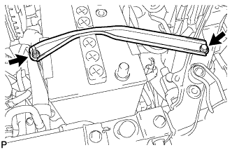 |
Detach the hook of the battery clamp from the front battery bracket, and then remove the battery clamp.
| 8. REMOVE BATTERY |
| 9. REMOVE BATTERY TRAY |
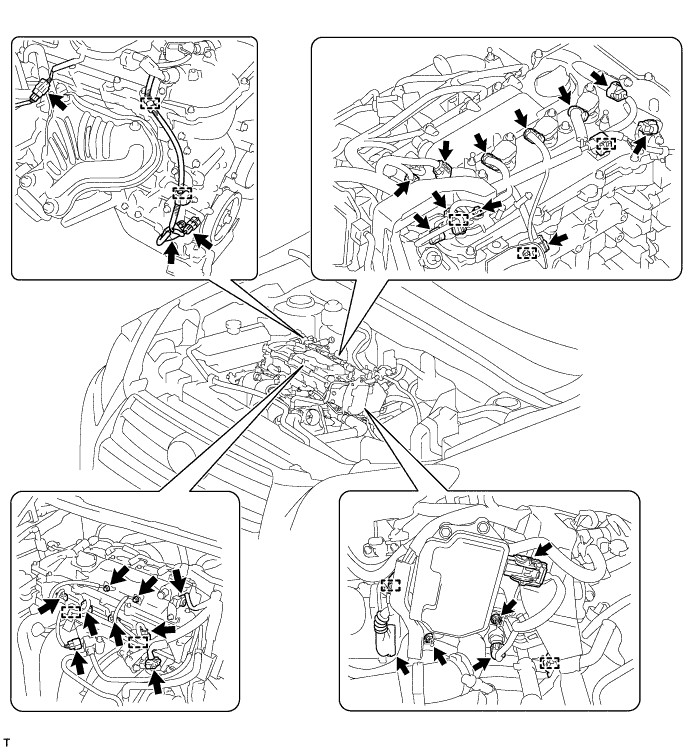
| 10. DISCONNECT ENGINE WIRE |
Detach the 9 clamps, and then disconnect the connectors.
Remove the 3 bolts and 2 nuts, and then disconnect the engine wire.
| 11. REMOVE AIR TUBE |
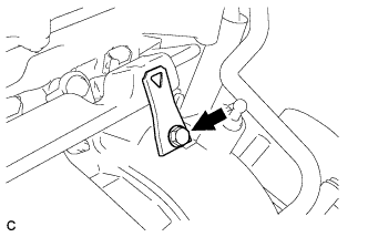
Disconnect the fuel vapor feed hose from the purge VSV.
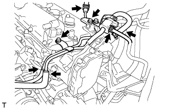 |
Disconnect the 2 union to connector tube hoses.
Disconnect the No. 2 air hose and No. 1 fuel vapor feed hose.
Remove the 2 bolts and air tube.
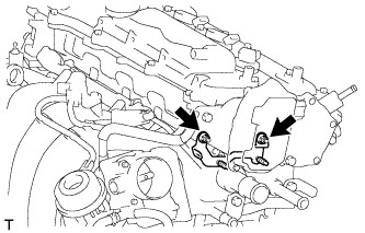
| 12. REMOVE WIRE HARNESS CLAMP BRACKET |
Remove the 2 nuts and wire harness clamp bracket.
 |
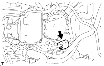
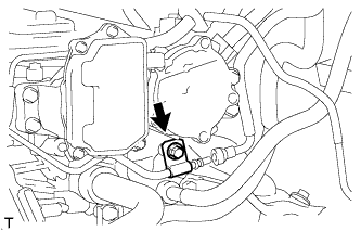
| 13. DISCONNECT FUEL TUBE SUB-ASSEMBLY |
Remove the No. 2 fuel pipe clamp.
 |
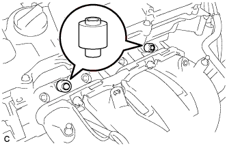
Wipe off any dirt on the fuel tube connector.
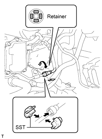 |
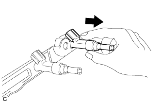
Hold the fuel tube connector, and then install SST.
- SST
- 09268-21010
Turn SST to align the retainer inside the fuel tube connector with the chamfered part of SST.
Insert SST into the fuel tube and hold it. Then push the fuel tube connector toward SST.
Mount the retainer of the fuel tube connector onto the chamfered part of SST.
Slide SST and the fuel tube connector together towards the fuel tube until they make a "click" sound, and then disconnect the fuel tube.
Text in Illustration *1 O-Ring *2 Retainer *3 Pipe *4 Nylon Tube *5 Fuel Tube Connector
 |
Drain the fuel remaining inside the fuel tube.
Cover the fuel tube and fuel pipe with a plastic bag to protect the disconnected part.
| 14. REMOVE FUEL DELIVERY PIPE SUB-ASSEMBLY |
Remove the bolt and wire harness bracket.
 |
Remove the 2 bolts.
 |
Remove the bolt and fuel delivery pipe.
 |
Remove the 2 No. 1 delivery pipe spacers.
 |
| 15. REMOVE FUEL INJECTOR ASSEMBLY |
Pull the 4 fuel injector assemblies out of the fuel delivery pipe sub-assembly.
 |
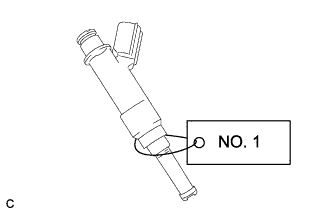
For reinstallation, attach a tag or label to the injector shaft.
- NOTICE:
- Prevent entry of foreign objects by covering the fuel injector with plastic bags.
 |
Remove the 4 injector vibration insulators.
 |