Lighting System Illumination Circuit
Lighting. Toyota Rav4. Aca30, 33, 38 Gsa33 Zsa30, 35
DESCRIPTION
WIRING DIAGRAM
INSPECTION PROCEDURE
PERFORM ACTIVE TEST USING INTELLIGENT TESTER (MAIN BODY ECU)
INSPECT FUSE (DOME)
INSPECT ROOM LIGHT ASSEMBLY
INSPECT ROOM LIGHT BULB
CHECK HARNESS AND CONNECTOR (BATTERY - ROOM LIGHT AND JUNCTION BLOCK)
INSPECT MAP LIGHT BULB
INSPECT MAP LIGHT
CHECK WIRE HARNESS (BATTERY - MAP LIGHT AND JUNCTION BLOCK)
INSPECT IGNITION KEY CYLINDER LIGHT
CHECK WIRE HARNESS (INSTRUMENT PANEL JUNCTION BLOCK - BATTERY)
LIGHTING SYSTEM - Illumination Circuit |
DESCRIPTION
The main body ECU receives information regarding the door courtesy switch and door lock position switch, and turns on the room light assembly.
WIRING DIAGRAM
INSPECTION PROCEDURE
| 1.PERFORM ACTIVE TEST USING INTELLIGENT TESTER (MAIN BODY ECU) |
Connect the intelligent tester to the DLC3.
Turn the ignition switch on (IG) and press the intelligent tester main switch ON.
Select the item below in the ACTIVE TEST and then check that the relay operates.
Main body ECUItem
| Test Details
| Diagnostic Note
|
Illumi Output
| Test Details:
Turn interior light and key illumination ON/OFF
Vehicle Condition:
Room light SW is in DOOR position and all doors are closed
| -
|
- OK:
- Headlights (LOW) come on.
| | PROCEED TO NEXT CIRCUIT INSPECTION SHOWN IN PROBLEM SYMPTOMS TABLE |
|
|
Remove the DOME fuse from the engine room No. 2 relay block.
Measure the resistance of the fuse.
- Standard resistance:
- Below 1 Ω
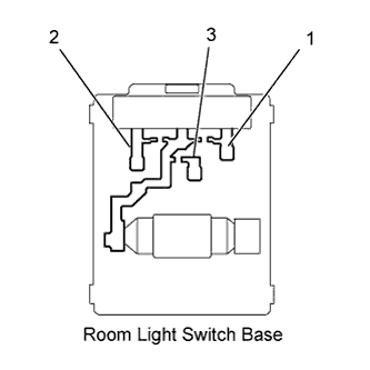
| 3.INSPECT ROOM LIGHT ASSEMBLY |
Remove the room light assembly.
Measure the resistance of the room light switch base.
- Standard resistance:
Tester Connection
| Switch Operation
| Specified Condition
|
1 - 2
1 - 3
| OFF
| 10 kΩ or higher
|
1 - 2
| DOOR
| Below 1 Ω
|
1 - 3
| ON
| Below 1 Ω
|
| | REPLACE ROOM LIGHT ASSEMBLY |
|
|
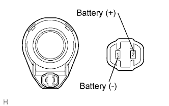
| 4.INSPECT ROOM LIGHT BULB |
Remove the room light assembly.
Connect the positive (+) lead from the battery to terminal 1 and the negative (-) lead to terminal 2, then check that the bulb illuminates when the switch is in the DOOR position.
- OK:
- Bulb illuminates.
Connect the positive (+) lead from the battery to terminal 1 and the negative (-) lead to terminal 3, then check that the bulb illuminates when the switch is in the ON position.
- OK:
- Bulb illuminates.
| 5.CHECK HARNESS AND CONNECTOR (BATTERY - ROOM LIGHT AND JUNCTION BLOCK) |
Disconnect the IK instrument panel junction block connector.
Measure the voltage of the wire harness side connector.
- Standard voltage:
Tester Connection
| Condition
| Specified Condition
|
IK-2 - Body ground
| Room light switch in DOOR position
| 10 to 14 V
|
| | REPAIR OR REPLACE HARNESS AND CONNECTOR |
|
|
Remove the map light assembly.
Connect the positive (+) lead from the battery to terminal 6 and the negative (-) lead to terminal 1, then check that the bulb illuminates when the switch is in the DOOR position.
- OK:
- Bulb illuminates.
Connect the positive (+) lead from the battery to terminal 6 and the negative (-) lead to terminal 7, then check that the bulb illuminates when the switch is in the ON position.
- OK:
- Bulb illuminates.
Remove the map light assembly.
Replace the map light bulb.
Inspect the map light.
Connect the positive (+) lead from the battery to terminal 6 and the negative (-) lead to terminal 1, then check that the light comes on when the switch is in the DOOR position.
- OK:
- Light comes on.
Connect the positive (+) lead from the battery to terminal 6 and the negative (-) lead to terminal 7, then check that the light comes on when the switch is in the ON position.
- OK:
- Light comes on.
| | REPLACE MAP LIGHT ASSEMBLY |
|
|
| 8.CHECK WIRE HARNESS (BATTERY - MAP LIGHT AND JUNCTION BLOCK) |
Disconnect the IK instrument panel junction block connector.
Measure the voltage of the wire harness side connector.
- Standard voltage:
Tester Connection
| Condition
| Specified Condition
|
IK-2 - Body ground
| Room light switch in DOOR position
| 10 to 14 V
|
| | REPAIR OR REPLACE HARNESS AND CONNECTOR |
|
|
| 9.INSPECT IGNITION KEY CYLINDER LIGHT |
RHD and w/o Entry and start system, w/ Engine immobiliser system
Remove the transponder key amplifier.
Connect the positive (+) lead from the battery to terminal 2 and the negative (-) lead to terminal 6, then check that the light comes on.
- OK:
- Light comes on.
w/ Entry and start system and w/o Engine immobiliser system
Remove the ignition key cylinder light.
Connect the positive (+) lead from the battery to terminal 2 and the negative (-) lead to terminal 1, then check that the light comes on.
- OK:
- Light comes on.
| | REPLACE IGNITION KEY CYLINDER LIGHT |
|
|
| 10.CHECK WIRE HARNESS (INSTRUMENT PANEL JUNCTION BLOCK - BATTERY) |
Disconnect the IE instrument panel junction block connector.
Measure the voltage of the wire harness side connector.
- Standard voltage:
Tester Connection
| Specified Condition
|
IE-27 (ILE) - Body ground
| 10 to 14 V
|
| | REPAIR OR REPLACE HARNESS AND CONNECTOR |
|
|
| OK |
|
|
|
| REPLACE INSTRUMENT PANEL JUNCTION BLOCK (MAIN BODY ECU) |
|