Cylinder Head -- Removal |
| 1. DISCHARGE FUEL SYSTEM PRESSURE |
- CAUTION:
- DISCHARGE FUEL SYSTEM PRESSURE procedures must be performed before disconnecting any part of the fuel system.
- After performing the DISCHARGE FUEL SYSTEM PRESSURE procedures, pressure will remain in the fuel line. When disconnecting the fuel line, place a cloth or equivalent over fittings to reduce the risk of fuel spray.
Remove the console box (RAV4_ACA30 RM000001RHJ00GX_01_0039.html).
Disconnect the connector.
 |
Start the engine. After the engine has stopped, turn the ignition switch off.
- HINT:
- DTC P0171 (system too lean) may be set.
Check that the engine does not start.
Remove the fuel tank cap, and let the air out of the fuel tank.
Connect the connector.
|
Install the console box (RAV4_ACA30 RM000001RHG00HX_01_0010.html).
| 2. DISCONNECT CABLE FROM NEGATIVE BATTERY TERMINAL |
- CAUTION:
- Wait at least 90 seconds after disconnecting the cable from the negative (-) battery terminal to prevent airbag and seat belt pretensioner activation.
| 3. REMOVE RADIATOR SUPPORT OPENING COVER |
| 4. REMOVE FRONT WHEEL RH |
| 5. REMOVE NO. 1 ENGINE UNDER COVER |
| 6. REMOVE FRONT FENDER APRON RH |
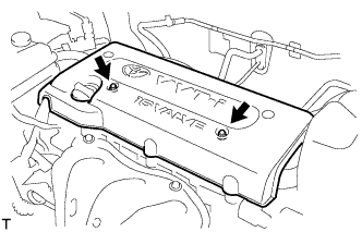
| 7. REMOVE NO. 1 ENGINE COVER |
Remove the 2 nuts and cover.
 |
| 8. DRAIN ENGINE COOLANT |
Loosen the radiator drain cock plug.
- HINT:
- Collect the coolant in a container and dispose of it according to the regulations in your area.
Remove the radiator reservoir cap.
- CAUTION:
- Do not remove the radiator reservoir cap while the engine and radiator are still hot. Pressurized, hot engine coolant and steam may be released and cause serious burns.
Loosen the cylinder block drain cock plug.

| 9. DRAIN ENGINE OIL |
Remove the oil filler cap.
Remove the oil drain plug and drain the oil into a container.
| 10. REMOVE AIR CLEANER CAP |
Disconnect the mass air flow meter connector.
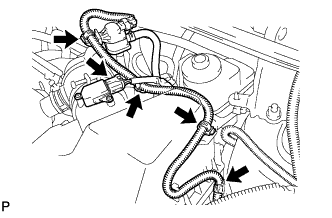 |
Disconnect the purge VSV connector.
Disconnect the 4 wire harness clamps.
Disconnect the No. 2 ventilation hose from the air cleaner hose.
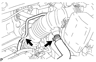 |
Disconnect the purge line hose from the clamp.
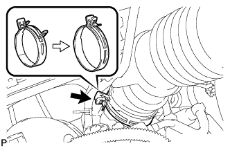
Lock the No. 1 air cleaner hose clamp, and then disconnect the No. 1 air cleaner hose from the throttle body.
 |
Unfasten the 2 hook clamps, and then remove the air cleaner cap.
 |
Remove the air cleaner filter element from the air cleaner case.
| 11. REMOVE THROTTLE BODY |
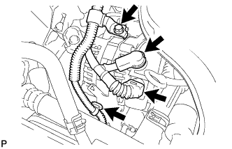
Disconnect the purge line hose from the throttle body.
 |
Disconnect the water by-pass hose from the throttle body.
Disconnect the No. 2 water by-pass hose from the throttle body.
for Type A:
Disconnect the No. 1 throttle body hose from the throttle body.
Disconnect the throttle position sensor and control motor connector.
Disconnect the wire harness clamp.
Disconnect the fuel tube from the clamp.
Remove the 4 bolts, and then remove the fuel pipe support and throttle body.
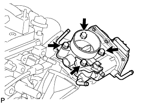 |
Remove the gasket from the intake manifold.
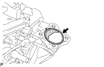 |
| 12. REMOVE FUEL DELIVERY PIPE SUB-ASSEMBLY |
Remove the 2 wire harness clamps.
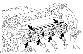 |
Disconnect the 4 fuel injector connectors.
Remove the 2 bolts and then pull out the fuel delivery pipe together with the 4 fuel injectors.
- NOTICE:
- Be careful not to drop the fuel injectors when removing the fuel delivery pipe.
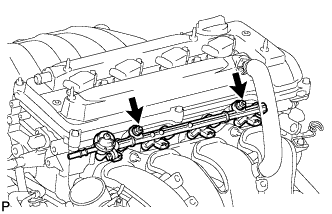 |
Remove the 2 delivery pipe spacers from the cylinder head.
 |
Remove the 4 insulators from the cylinder head.
| 13. REMOVE INTAKE MANIFOLD |
Disconnect the union to check valve hose from the brake booster.
Disconnect the camshaft timing oil control valve connector.
 |
Remove the wire harness clamp.
Remove the union to check valve hose from the vacuum hose clamp.
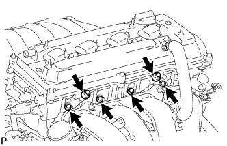
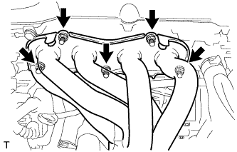
Remove the 5 bolts, 2 nuts and intake manifold.
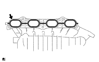
Remove the gasket from the intake manifold.
 |
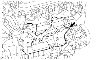
| 14. REMOVE INTAKE MANIFOLD INSULATOR |
Remove the intake manifold insulator from the cylinder block.
 |
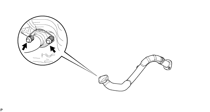
| 15. REMOVE FRONT EXHAUST PIPE |
Remove the 2 bolts, 2 compression springs and front exhaust pipe.
Remove the gasket from the exhaust manifold.
| 16. REMOVE OIL DIPSTICK |
| 17. REMOVE OIL DIPSTICK GUIDE |
Remove the bolt and guide.
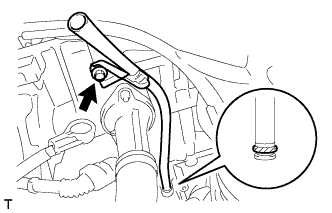 |
Remove the O-ring from the guide.
| 18. REMOVE MANIFOLD STAY |
Remove the bolt, nut and stay.
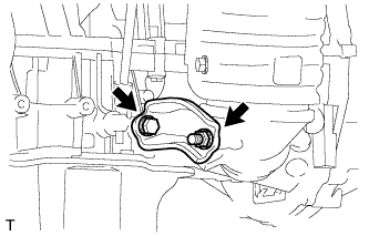 |
| 19. REMOVE NO. 2 MANIFOLD STAY |
Remove the bolt, nut and stay.
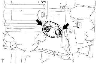 |
| 20. REMOVE NO. 1 EXHAUST MANIFOLD HEAT INSULATOR |
Remove the 4 bolts and heat insulator.
 |
| 21. REMOVE EXHAUST MANIFOLD CONVERTER SUB-ASSEMBLY |
Disconnect the air-fuel ratio sensor connector.
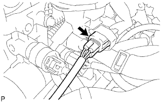 |
Remove the 5 nuts, manifold converter and gasket.
 |
| 22. DISCONNECT NO. 1 RADIATOR HOSE |
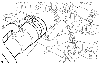
Disconnect the hose from the cylinder head.
 |
| 23. DISCONNECT ENGINE WIRE |
Disconnect the radio setting condenser connector.
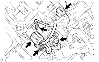 |
Disconnect the engine oil pressure switch connector.
Disconnect the engine coolant temperature sensor connector.
Disconnect the camshaft position sensor connector.
Remove the bolt and ground cable.
| 24. REMOVE FRONT SUSPENSION MEMBER REINFORCEMENT RH |
Remove the 4 bolts and reinforcement RH.
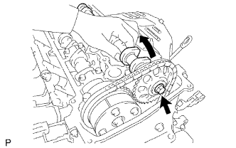
| 25. REMOVE FAN & GENERATOR V BELT |
Using SST and 19 mm socket wrench, loosen the V-ribbed belt tensioner arm clockwise, then remove the fan and generator V belt.
- SST
- 09216-42010
- NOTICE:
- Be sure to connect SST and the tools so that they are in line during use.
- When retracting the tensioner, turn it clockwise slowly for 3 seconds or more. Do not apply force rapidly.
- After the tensioner is fully retracted, do not apply force any more than necessary.
 |
| 26. REMOVE IDLER PULLEY |
Loosen the 2 bolts and remove the idler bracket with the 2 bolts.
 |
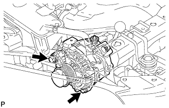
| 27. REMOVE GENERATOR ASSEMBLY |
 |
Disconnect the generator connector.
Remove the terminal cap.
Remove the nut and disconnect the generator wire.
Remove the bolt and wire harness clamp bracket.
Remove the wire harness clamps.
Remove the 2 bolts and generator.
 |
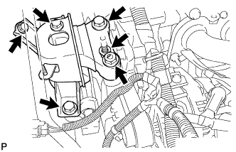
| 28. REMOVE ENGINE MOUNTING INSULATOR RH |
Place a transmission jack underneath the engine, then put a wooden block on the jack.
 |
Remove the 4 bolts, 2 nuts and engine mounting insulator RH.
- NOTICE:
- Do not apply excessive force to the return tube when removing the engine mounting insulator RH.
- HINT:
- Keep clearance by lowering the engine using the transmission jack when removing the engine mounting insulator FR.
 |
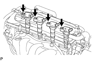
| 29. REMOVE IGNITION COIL ASSEMBLY |
Disconnect the 4 ignition coil connectors.
Remove the 4 bolts and 4 ignition coils.
 |
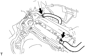
| 30. REMOVE CYLINDER HEAD COVER SUB-ASSEMBLY |
Disconnect the 2 ventilation hoses from the cylinder head cover.
 |
Remove the 2 bolts and disconnect the 2 engine wires.
 |
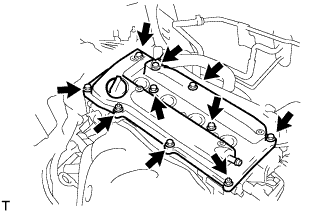
Remove the 8 bolts, 2 nuts and cylinder head cover.
 |
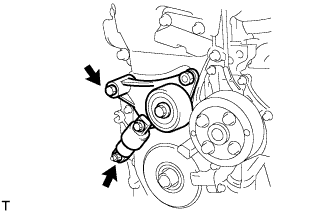
| 31. REMOVE V-RIBBED BELT TENSIONER ASSEMBLY |
Lift the engine upward using the transmission jack.
- NOTICE:
- Do not lift the engine more than necessary.
Remove the bolt, nut and V-ribbed belt tensioner.
 |
| 32. REMOVE CRANKSHAFT POSITION SENSOR |
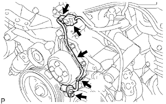 |
Disconnect the sensor connector.
Remove the connector clamp.
Remove the wire harness from the wire harness clamp bracket.
Remove the wire harness clamp.
Remove the bolt and sensor.
| 33. REMOVE OIL PAN SUB-ASSEMBLY |
Install the No. 1 and No. 2 engine hangers with the bolts.
- Torque:
- 38 N*m{387 kgf*cm, 28 ft.*lbf}
Part No. Item Part No. No. 1 engine hanger 12281-28010 No. 2 engine hanger 12282-28010 Bolt 91512-61020
 |
Attach the sling device to the engine hangers and chain block.
Remove the 12 bolts and 2 nuts.
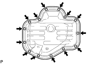 |
Insert the blade of an oil pan seal cutter between the crankcase, chain cover and oil pan and cut off the applied sealer and remove the oil pan.
- NOTICE:
- Be careful not to damage the contact surface of the crankcase, chain cover and oil pan.
 |
| 34. SET NO. 1 CYLINDER TO TDC/COMPRESSION |
Turn the crankshaft pulley until its groove and the timing mark "0" of the timing chain cover are aligned.
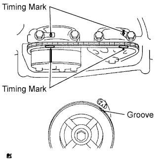 |
Check that each timing mark of the camshaft timing gear and sprocket is aligned with each timing mark located on the No. 1 and No. 2 bearing caps as shown in the illustration.
If not, turn the crankshaft by 1 revolution (360°) to align the timing marks as above.
| 35. REMOVE NO. 2 CAMSHAFT |
Place paint marks on the chain in alignment with the timing marks on the camshaft timing gear and camshaft timing sprocket.
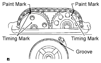 |
Remove the 2 nuts, tensioner and gasket.
 |
While holding the camshaft with a wrench, loosen the camshaft timing set bolt.
 |
Using several steps, uniformly loosen and remove the 10 bearing cap bolts in the sequence shown in the illustration.
 |
Remove the 5 bearing caps.
While holding the No. 2 camshaft by hand, remove the camshaft timing sprocket set bolt.
 |
Remove the camshaft timing sprocket from the No. 2 camshaft with the timing chain wrapped on the sprocket.
Remove the camshaft timing sprocket from the timing chain.
| 36. REMOVE CAMSHAFT |
Using several steps, uniformly loosen and remove the 10 bearing cap bolts in the sequence shown in the illustration.
 |
Remove the 5 bearing caps.
Remove the camshaft and camshaft timing gear while holding the timing chain by hand.
Tie the timing chain with a string as shown in the illustration.
- NOTICE:
- Be careful not to drop anything inside the timing chain cover.
 |
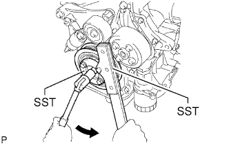
| 37. REMOVE CRANKSHAFT PULLEY |
Using SST, fix the pulley in place and loosen the pulley bolt.
- SST
- 09213-54015(91651-60855)
09330-00021
 |
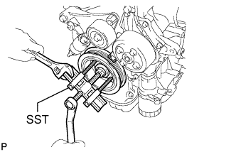
Remove the crankshaft pulley.
- HINT:
- If necessary, remove the pulley with SST and the pulley bolt.
- SST
- 09950-50013(09951-05010,09952-05010,09953-05020,09954-05021)
09950-40011(09957-04010)
 |
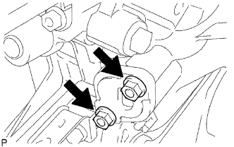
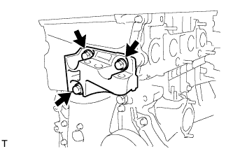
| 38. REMOVE ENGINE MOUNTING BRACKET RH |
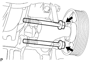
Remove the 3 bolts and engine mounting bracket RH.
 |
| 39. REMOVE TIMING CHAIN COVER SUB-ASSEMBLY |
Using an E10 "torx" socket, remove the stud bolt for the V-ribbed belt tensioner.
 |
Remove the 12 bolts and 2 nuts.
 |
Remove the timing chain cover by prying the portions between the timing chain cover, cylinder head and cylinder block with a screwdriver.
- NOTICE:
- Be careful not to damage the contact surfaces of the timing chain cover, cylinder head and cylinder block.
 |
| 40. REMOVE NO. 1 CRANKSHAFT POSITION SENSOR PLATE |
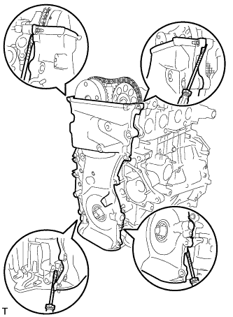
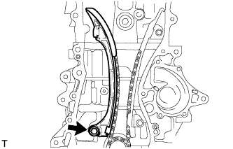
| 41. REMOVE TIMING CHAIN GUIDE |
Remove the bolt and timing chain guide.
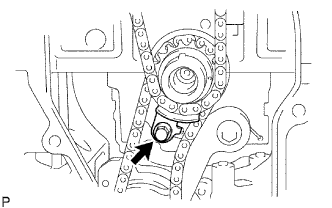 |
| 42. REMOVE CHAIN TENSIONER SLIPPER |
Remove the bolt and chain tensioner slipper.
 |
| 43. REMOVE CHAIN SUB-ASSEMBLY |
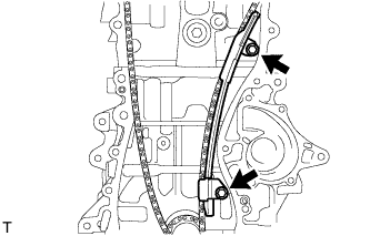
| 44. REMOVE NO. 1 CHAIN VIBRATION DAMPER |
Remove the 2 bolts and chain vibration damper.
 |
| 45. REMOVE CAMSHAFT TIMING OIL CONTROL VALVE ASSEMBLY |
Disconnect the oil control valve connector.
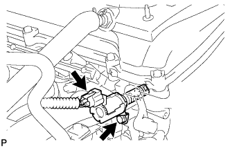 |
Remove the bolt and oil control valve.
| 46. REMOVE CAMSHAFT TIMING GEAR ASSEMBLY |
Clamp the camshaft in a vise, and make sure that the camshaft timing gear does not rotate.
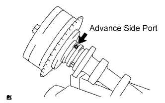 |
Cover all the oil ports with vinyl tape except the advance side port shown in the illustration.
Apply air pressure of 100 kPa (1.0 kgf/cm2, 14 psi) to the oil path, then turn the camshaft timing gear to the advance direction (counterclockwise) by hand.
- CAUTION:
- Cover the paths with a shop rag to avoid oil splashes.
- HINT:
- Depending on the air pressure, the camshaft timing gear will turn to the advance angle side without applying force by hand. Also, under the condition that the pressure is difficult to apply because of air leakage from the port, there may be the case that the lock pin is difficult to release.
 |
Remove the flange bolt of the camshaft timing gear.
- NOTICE:
- Be sure not to remove the other 4 bolts.
- When reusing the camshaft timing gear, release the straight lock pin first, then install the gear.
 |
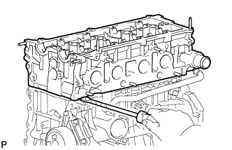
| 47. REMOVE CYLINDER HEAD SUB-ASSEMBLY |
Using several steps, uniformly loosen and remove the 10 cylinder head bolts and 10 plate washers with a 10 mm bi-hexagon wrench in the sequence shown in the illustration.
- NOTICE:
- Head warpage or cracking could result from removing the bolts in the wrong order.
 |
Using a screwdriver, pry between the cylinder head and cylinder block, and remove the cylinder head.
- NOTICE:
- Be careful not to damage the contact surfaces of the cylinder head and cylinder block.
 |
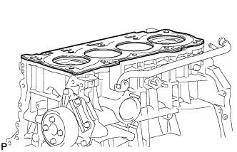
| 48. REMOVE CYLINDER HEAD GASKET |
 |