Cylinder Head -- Inspection |
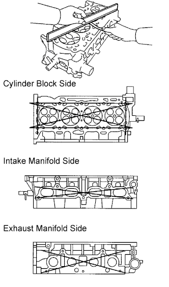
| 1. INSPECT CYLINDER HEAD FOR WARPAGE |
Using a precision straightedge and a feeler gauge, measure the surface that is in contact with the cylinder block and the manifolds for warpage.
- Maximum warpage:
- 0.08 mm (0.0032 in.)
 |
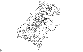
| 2. INSPECT CYLINDER HEAD FOR CRACKS |
Using a dye penetrant, inspect the combustion chamber, intake ports, exhaust ports and cylinder block surface for cracks.
If cracked, replace the cylinder head.
 |
| 3. INSPECT VALVE SEAT |
Apply a light coat of Prussian blue (or white lead) to the valve face.
Lightly press the valve against the seat.
- NOTICE:
- Do not turn the valve.
Check the valve face and seat in accordance with the following procedure.
If blue appears 360°around the face, the valve is concentric. If not, replace the valve.
If blue appears 360°around the valve seat, the guide and face are concentric. If not, resurface the valve seat (RAV4_ACA30 RM000001B2L00FX_01_0002.html).
Check that the seat contact is in the middle of the valve face with a width.
- Standard width:
Item Standard Condition Intake 1.0 to 1.4 mm (0.0039 to 0.0551 in.) Exhaust 1.2 to 1.6 mm (0.0472 to 0.0630 in.)
 |
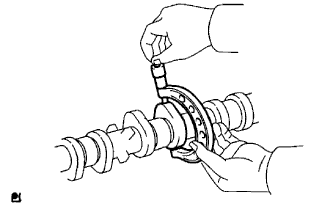
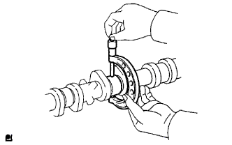
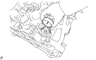
| 4. INSPECT CAMSHAFT TIMING GEAR ASSEMBLY |
Check the lock of the camshaft timing gear.
Clamp the camshaft in a vise, and confirm that the camshaft timing gear is locked.
- NOTICE:
- Be careful not to damage the camshaft.
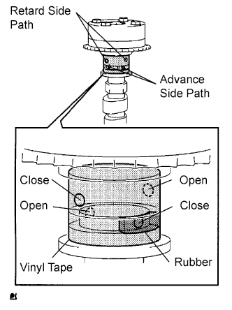 |
Release the lock pin.
Cover the 4 oil paths of the cam journal with vinyl tape as shown in the illustration.
- HINT:
- The 2 advance side paths are provided in the groove of the camshaft. Plug one of the paths with a rubber piece.
Break through the tape of the advance side path and the retard side path on the opposite side of the groove.
Apply approximately 200 kPa (2.0 kgf/cm2, 28 psi) of air pressure to the paths whose tape was broken in the procedure above.
- CAUTION:
- Some oil spraying will occur. Contain the spray with a shop rag.
Check that the camshaft timing gear revolves in the advance direction when weakening the air pressure of the retard side path.
- OK:
- Gear rotates in advance direction.
- HINT:
- This operation releases the lock pin for the extreme retard position.
When the camshaft timing gear reaches the extreme advance position, remove the air gun from the retard side path and advance side path, in that order.
- NOTICE:
- Do not remove the air gun from the advance side path first. The gear may abruptly shift in the retard direction and break the lock pin.

Check for smooth rotation.
Rotate the camshaft timing gear within its movable range several times, but do not turn it to the extreme retard position. Check that the gear rotates smoothly.
- OK:
- Gear rotates in advance direction.
- NOTICE:
- Do not use an air gun to perform the smooth operation check.
Check the lock in the extreme retard position.
Confirm that the camshaft timing gear is locked at the extreme retard position.
| 5. INSPECT CAMSHAFT |
Inspect the camshaft for runout.
Place the camshaft on V-blocks.
Using a dial indicator, measure the circle runout at the center journal.
- Maximum circle runout:
- 0.03 mm (0.0012 in.)
 |
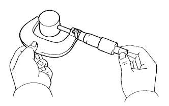
Inspect the cam lobes.
Using a micrometer, measure the cam lobe height.
- Standard cam lobe height:
- 47.306 to 47.406 mm (1.8624 to 1.8664 in.)
- Minimum cam lobe height:
- 47.196 mm (1.8581 in.)
 |
Inspect the camshaft journals.
Using a micrometer, measure the journal diameter.
- Standard journal diameter:
Journal Position Specified Condition No. 1 35.971 to 35.985 mm (1.4162 to 1.4167 in.) Other 22.959 to 22.975 mm (0.9039 to 0.9045 in.)
 |
| 6. INSPECT NO. 2 CAMSHAFT |
Inspect the camshaft for runout.
Place the camshaft on V-blocks.
Using a dial indicator, measure the circle runout at the center journal.
- Maximum circle runout:
- 0.03 mm (0.0012 in.)
|
Inspect the cam lobes.
Using a micrometer, measure the cam lobe height.
- Standard cam lobe height:
- 45.983 to 46.083 mm (1.8104 to 1.8143 in.)
- Minimum cam lobe height:
- 45.873 mm (1.8060 in.)
|
Inspect the camshaft journals.
Using a micrometer, measure the journal diameter.
- Standard journal diameter:
Journal Position Specified Condition No. 1 35.971 to 35.985 mm (1.4162 to 1.4167 in.) Other 22.959 to 22.975 mm (0.9039 to 0.9045 in.)
|
| 7. INSPECT CAMSHAFT OIL CLEARANCE |
Clean the 10 bearing caps and camshaft journals.
 |
Place the 2 camshafts on the cylinder head.
Lay a strip of Plastigage across each of the camshaft journals.
Install the 10 bearing caps (RAV4_ACA30 RM000001AN500TX_01_0004.html).
- NOTICE:
- Do not turn the camshaft.
Remove the 10 bearing caps for No. 2 camshaft (RAV4_ACA30 RM000001AN800UX_01_0057.html) and for camshaft (RAV4_ACA30 RM000001AN800UX_01_0058.html).
Measure the Plastigage at its widest point.
- Standard oil clearance:
Item Standard Condition Intake No. 1 journal 0.007 to 0.038 mm (0.0003 to 0.0015 in.) Exhaust No. 1 journal 0.040 to 0.079 mm (0.0016 to 0.0031 in.) Other journal 0.025 to 0.062 mm (0.0010 to 0.0024 in.)
- Maximum oil clearance:
Item Standard Condition Intake No. 1 journal 0.07 mm (0.0028 in.) Other journal 0.10 mm (0.0039 in.)
- NOTICE:
- Completely remove the Plastigage after the measurement.
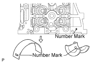
If the oil clearance on the other journals id greater than the maximum, replace the cylinder head sub-assembly or the camshaft.- Standard cylinder head journal bore diameter:
Mark Standard Condition Mark 1 40.000 to 40.008 mm (1.5748 to 1.5751 in.) Mark 2 40.009 to 40.017 mm (1.5752 to 1.5755 in.) Mark 3 40.018 to 40.025 mm (1.5755 to 1.5758 in.)
- Standard bearing center wall thickness:
Mark Standard Condition Mark 1 2.000 to 2.004 mm (0.0787 to 0.0789 in.) Mark 2 2.005 to 2.008 mm (0.0789 to 0.0791 in.) Mark 3 2.009 to 2.012 mm (0.0791 to 0.0792 in.)
- Standard camshaft journal diameter:
- 35.971 to 35.985 mm (1.4162 to 1.4167 in.)
 |
| 8. INSPECT CAMSHAFT THRUST CLEARANCE |
Install the 2 camshafts (RAV4_ACA30 RM000001AN500TX_01_0004.html).
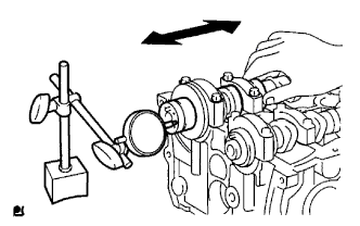 |
Using a dial indicator, measure the thrust clearance while moving the camshaft back and forth.
- Standard thrust clearance:
Item Standard Condition Intake 0.040 to 0.095 mm (0.0016 to 0.0037 in.) Exhaust 0.080 to 0.135 mm (0.0032 to 0.0053 in.)
- Maximum thrust clearance:
Item Standard Condition Intake 0.11 mm (0.0043 in.) Exhaust 0.15 mm (0.0059 in.)
If damage is found on the camshaft thrust surfaces, replace the camshaft.
| 9. INSPECT VALVE LIFTER |
Using a micrometer, measure the lifter diameter.
- Standard lifter diameter:
- 30.966 to 30.976 mm (1.2191 to 1.2195 in.)
 |
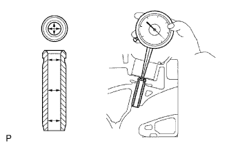
| 10. INSPECT VALVE LIFTER OIL CLEARANCE |
Using a caliper gauge, measure the valve lifter bore diameter of the cylinder head.
- Standard lifter bore diameter:
- 31.009 to 31.025 mm (1.2208 to 1.2215 in.)
 |
Subtract the valve lifter diameter measurement from the valve lifter bore diameter measurement.
- Standard oil clearance:
- 0.033 to 0.059 mm (0.0013 to 0.0023 in.)
- Maximum oil clearance:
- 0.079 mm (0.0031 in.)
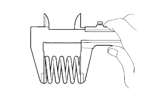
| 11. INSPECT INNER COMPRESSION SPRING |
Using vernier calipers, measure the free length of the valve spring.
- Standard free length:
- 47.43 mm (1.8673 in.)
 |
Using a steel square, measure the deviation of the inner compression spring.
- Maximum deviation:
- 1.6 mm (0.063 in.)
- Maximum angle (Reference):
- 2°
 |
| 12. INSPECT INTAKE VALVE |
Using a gasket scraper, chip off any carbon on the valve head.
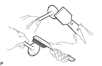 |
Using a wire brush, thoroughly clean the valve.
Using a vernier caliper, measure the valve overall length.
- Standard overall length:
- 101.71 mm (4.0043 in.)
- Minimum overall length:
- 101.21 mm (3.9846 in.)
 |
Using a micrometer, measure the diameter of the valve stem.
- Standard valve stem diameter:
- 5.470 to 5.485 mm (0.2154 to 0.2159 in.)
 |
Using a vernier caliper, measure the valve head margin thickness.
- Standard margin thickness:
- 1.25 mm (0.0492 in.)
- Minimum margin thickness:
- 1.05 mm (0.0413 in.)
 |
| 13. INSPECT EXHAUST VALVE |
Using a gasket scraper, chip off any carbon on the valve head.
|
Using a wire brush, thoroughly clean the valve.
Using vernier calipers, measure the valve overall length.
- Standard overall length:
- 101.15 mm (3.9823 in.)
- Minimum overall length:
- 100.70 mm (3.9646 in.)
|
Using a micrometer, measure the diameter of the valve stem.
- Standard valve stem diameter:
- 5.465 to 5.480 mm (0.2152 to 0.2158 in.)
|
Using vernier calipers, measure the valve head margin thickness.
- Standard margin thickness:
- 1.40 mm (0.0551 in.)
- Minimum margin thickness:
- 1.20 mm (0.0472 in.)
|
| 14. INSPECT INTAKE VALVE GUIDE BUSH |
Using a caliper gauge, measure the inside diameter of the guide bush.
- Standard bush inside diameter:
- 5.510 to 5.530 mm (0.2169 to 0.2177 in.)
 |
Subtract the valve stem diameter measurement from the guide bush inside diameter measurement.
- Standard oil clearance:
- 0.025 to 0.060 mm (0.0010 to 0.0024 in.)
- Maximum oil clearance:
- 0.08 mm (0.0032 in.)
| 15. INSPECT EXHAUST VALVE GUIDE BUSH |
Using a caliper gauge, measure the inside diameter of the guide bush.
- Standard bush inside diameter:
- 5.510 to 5.530 mm (0.2169 to 0.2177 in.)
|
Subtract the valve stem diameter measurement from the guide bush inside diameter measurement.
- Standard oil clearance:
- 0.030 to 0.065 mm (0.0012 to 0.0026 in.)
- Maximum oil clearance:
- 0.10 mm (0.004 in.)
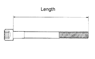
| 16. INSPECT CYLINDER HEAD SET BOLT |
Using a vernier caliper, measure the length of the head bolts from the seat to the end.
- Standard bolt length:
- 161.3 to 162.7 mm (6.350 to 6.406 in.)
- Maximum bolt length:
- 164.2 mm (6.465 in.)
 |
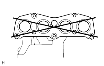
| 17. INSPECT EXHAUST MANIFOLD |
Using a precision straightedge and a feeler gauge, measure the surface contacting the cylinder head for warpage.
- Maximum warpage:
- 0.70 mm (0.028 in.)
 |