Cruise Control System Cruise Control Switch Circuit
DESCRIPTION
WIRING DIAGRAM
INSPECTION PROCEDURE
READ VALUE USING INTELLIGENT TESTER (CRUISE CONTROL MAIN SWITCH)
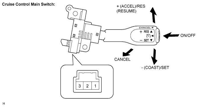
INSPECT CRUISE CONTROL MAIN SWITCH
CHECK WIRE HARNESS (CRUISE CONTROL MAIN SWITCH - SPIRAL CABLE)
INSPECT SPIRAL CABLE
CHECK WIRE HARNESS (SPIRAL CABLE - ECM AND BODY GROUND)
CRUISE CONTROL SYSTEM - Cruise Control Switch Circuit |
DESCRIPTION
This circuit sends signals to the ECM depending on the cruise control main switch condition. The battery supplies positive (+) battery voltage to the cruise control main switch. Then terminal CCS of the ECM receives the voltage according to the switch condition.
WIRING DIAGRAM
INSPECTION PROCEDURE
| 1.READ VALUE USING INTELLIGENT TESTER (CRUISE CONTROL MAIN SWITCH) |
Connect the intelligent tester to the DLC3.
Turn the ignition switch on (IG) and turn the intelligent tester main switch on.
Check the Data List for proper functioning of the cruise control main switch.
- ECM (Cruise Control):
Item
| Measurement Item / Display (Range)
| Normal Condition
| Diagnostic Note
|
Main SW (Main)
| Cruise control main switch signal (Main CPU) / ON or OFF
| ON: Cruise control main switch is ON (Main CPU)
OFF: Cruise control main switch is OFF (Main CPU)
| -
|
Cancel SW
| CANCEL switch signal / ON or OFF
| ON: CANCEL switch ON
OFF: CANCEL switch OFF
| -
|
SET/COAST SW
| - / SET switch signal / ON or OFF
| ON: - / SET switch ON
OFF: - / SET switch OFF
| -
|
RES/ACC SW
| + / RES switch signal / ON or OFF
| ON: + / RES switch ON
OFF: + / RES switch OFF
| -
|
- OK:
- When cruise control main switch operation is performed, the results will be same as above.
ResultResult
| Proceed to
|
OK
| A
|
NG (All items are defective)
| B
|
NG (1 to 3 items are defective)
| C
|
| | PROCEED TO NEXT CIRCUIT INSPECTION SHOWN IN PROBLEM SYMPTOMS TABLE |
|
|
| | REPLACE CRUISE CONTROL MAIN SWITCH |
|
|
| 2.INSPECT CRUISE CONTROL MAIN SWITCH |
Remove the cruise control main switch.
Measure the resistance according to the value(s) in the table below.
- Standard resistance:
Tester Connection
| Switch Condition
| Specified Condition
|
3 (CCS) - 1 (ECC)
| Neutral
| 10 kΩ or higher
|
+ (ACCEL)/RES (RESUME)
| 235 to 245 Ω
|
- (COAST)/SET
| 617 to 643 Ω
|
CANCEL
| 1509 to 1571 Ω
|
Main Switch ON
| Below 1 Ω
|
| | REPLACE CRUISE CONTROL MAIN SWITCH |
|
|
| 3.CHECK WIRE HARNESS (CRUISE CONTROL MAIN SWITCH - SPIRAL CABLE) |
Disconnect the A switch connector.
Disconnect the B cable connector.
Measure the resistance according to the value(s) in the table below.
- Standard resistance:
Tester Connection
| Condition
| Specified Condition
|
A-3 - B-3
| Always
| Below 1 Ω
|
A-1 - B-4
| Always
| Below 1 Ω
|
| | REPAIR OR REPLACE HARNESS OR CONNECTOR |
|
|
- NOTICE:
- The spiral cable is an important part of the SRS airbag system. Incorrect removal or installation of the spiral cable may prevent the airbag from deploying.
Remove the spiral cable.
Measure the resistance according to the value(s) in the table below.
- Standard resistance:
Tester Connection
| Spiral Cable Position
| Specified Condition
|
3 (CCS) - 1 (CCS)
| Center
| Below 1 Ω
|
2.5 rotations to the left
|
2.5 rotations to the right
|
4 (ECC) - 2 (ECC)
| Center
| Below 1 Ω
|
2.5 rotations to the left
|
2.5 rotations to the right
|
- HINT:
- The spiral cable makes a maximum of approximately 5 rotations.
| 5.CHECK WIRE HARNESS (SPIRAL CABLE - ECM AND BODY GROUND) |
Disconnect the E10 cable connector.
Disconnect the A12 ECM connector.
Measure the resistance of the wire harness side connectors.
- Standard resistance:
Tester Connection
| Specified Condition
|
E10-1 (CCS) - A12-40 (CCS)
| Below 1 Ω
|
E10-2 (ECC) - Body ground
|
| | REPAIR OR REPLACE HARNESS OR CONNECTOR |
|
|