Automatic Transaxle Unit Reassembly
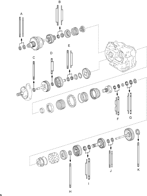
BEARING POSITION
INSTALL DIFFERENTIAL GEAR LUBE APPLY TUBE
INSTALL NO. 1 TRANSAXLE CASE PLUG
INSTALL UNDERDRIVE OUTPUT SHAFT OIL SEAL RING
INSTALL UNDERDRIVE CYLINDRICAL ROLLER BEARING
INSTALL UNDERDRIVE CLUTCH DRUM OIL SEAL RING
INSTALL NEEDLE ROLLER BEARING
INSTALL UNDERDRIVE BRAKE PISTON
INSTALL UNDERDRIVE BRAKE RETURN SPRING SUB-ASSEMBLY
INSTALL NO. 2 BREATHER PLUG
INSTALL COUNTER DRIVE GEAR BEARING
INSTALL COUNTER DRIVE GEAR
INSTALL 1ST AND REVERSE BRAKE PISTON
INSTALL 1ST AND REVERSE BRAKE RETURN SPRING SUB-ASSEMBLY
INSTALL FRONT PLANETARY RING GEAR
INSTALL FRONT PLANETARY GEAR ASSEMBLY
INSTALL INPUT SUN GEAR
INSTALL REAR PLANETARY GEAR ASSEMBLY
INSTALL 1ST AND REVERSE BRAKE CLUTCH DISC
INSPECT PACK CLEARANCE OF FIRST AND REVERSE BRAKE
INSTALL 2ND BRAKE PISTON ASSEMBLY
INSTALL ONE-WAY CLUTCH SLEEVE OUTER
INSTALL ONE-WAY CLUTCH ASSEMBLY
INSTALL NO. 1 PLANETARY CARRIER THRUST WASHER
REMOVE REAR PLANETARY SUN GEAR ASSEMBLY
INSTALL 2ND BRAKE CLUTCH DISC
INSPECT PACK CLEARANCE OF 2ND BRAKE
INSTALL OVERDRIVE DIRECT CLUTCH HUB SUB-ASSEMBLY
INSTALL DIRECT CLUTCH ASSEMBLY
INSTALL NO. 1 GOVERNOR APPLY GASKET
INSTALL BRAKE APPLY TUBE
INSTALL NEEDLE ROLLER BEARING
INSTALL REAR CLUTCH OIL SEAL RING OUTER
INSTALL NO. 1 TRANSAXLE CASE PLUG
INSTALL REAR TRANSAXLE COVER SUB-ASSEMBLY
INSTALL NO. 2 UNDERDRIVE CLUTCH DISC
INSPECT PACK CLEARANCE OF UNDERDRIVE BRAKE
INSPECT UNDERDRIVE ONE-WAY CLUTCH ASSEMBLY
INSTALL UNDERDRIVE ONE-WAY CLUTCH ASSEMBLY
INSTALL UNDERDRIVE CLUTCH ASSEMBLY
INSTALL PARKING LOCK PAWL
INSTALL UNDERDRIVE PLANETARY GEAR ASSEMBLY
INSTALL MULTIPLE DISC CLUTCH HUB
INSTALL FORWARD CLUTCH ASSEMBLY
INSTALL OVERDRIVE BRAKE GASKET
INSTALL DIFFERENTIAL GEAR ASSEMBLY
INSTALL NO. 2 THRUST BEARING UNDERDRIVE RACE
INSTALL THRUST NEEDLE ROLLER BEARING
INSTALL OIL PUMP ASSEMBLY
INSTALL TRANSAXLE HOUSING
INSPECT INPUT SHAFT END PLAY
SECURE AUTOMATIC TRANSAXLE ASSEMBLY
INSTALL MANUAL VALVE LEVER SHAFT OIL SEAL
INSTALL PARKING LOCK ROD SUB-ASSEMBLY
INSTALL MANUAL VALVE LEVER SUB-ASSEMBLY
INSTALL MANUAL VALVE LEVER SHAFT RETAINER SPRING
INSTALL PARKING LOCK PAWL BRACKET
INSTALL MANUAL DETENT SPRING SUB-ASSEMBLY
INSTALL B-3 ACCUMULATOR PISTON
INSTALL REVERSE CLUTCH ACCUMULATOR PISTON
INSTALL C-3 ACCUMULATOR PISTON
INSTALL CHECK BALL BODY
INSTALL BRAKE DRUM GASKET
INSTALL TRANSAXLE CASE 2ND BRAKE GASKET
INSTALL NO. 1 GOVERNOR APPLY GASKET
INSTALL TRANSMISSION WIRE
CONNECT TRANSMISSION WIRE
INSTALL TRANSMISSION VALVE BODY ASSEMBLY
INSTALL VALVE BODY OIL STRAINER ASSEMBLY
INSTALL AUTOMATIC TRANSAXLE OIL PAN SUB-ASSEMBLY
INSTALL NO. 1 TRANSAXLE CASE PLUG
INSTALL SPEEDOMETER DRIVEN HOLE COVER SUB-ASSEMBLY
INSTALL SPEED SENSOR
INSTALL OIL COOLER INLET TUBE ELBOW
INSTALL OIL COOLER OUTLET TUBE ELBOW
INSTALL BREATHER PLUG HOSE
INSTALL PARK/NEUTRAL POSITION SWITCH ASSEMBLY
Automatic Transaxle Unit -- Reassembly |
- Standard bearing position:
Mark
| Front Race Diameter
Inside / Outside
| Thrust Bearing Diameter
Inside / Outside
| Rear Race Diameter
Inside / Outside
|
A
| -
| 57.2 mm (2.252 in.) / 84.96 mm (3.3449 in.)
| 56.4 mm (2.220 in.) / 83.0 mm (3.268 in.)
|
B
| -
| 37.73 mm (1.4854 in.) / 58.0 mm (2.283 in.)
| -
|
C
| -
| 33.85 mm (1.3327 in.) / 52.2 mm (2.055 in.)
| -
|
D
| 24.94 mm (0.982 in.)
| 23.5 mm (0.925 in.) / 44.0 mm (1.732 in.)
| -
|
E
| -
| 36.3 mm (1.429 in.) / 51.93 mm (2.0445 in.)
| 34.5 mm (1.358 in.) / 48.35 mm (1.904 in.)
|
F
| 34.35 mm (1.3524 in.) / 56.57 mm (2.2272 in.)
| 32.45 mm (1.2776 in.) / 56.48 mm (2.2236 in.)
| -
|
G
| 40.15 mm (1.5807 in.) / 59.25 mm (2.3327 in.)
| 38.65 mm (1.5217 in.) / 59.79 mm (2.3539 in.)
| 38.65 mm (1.5217 in.) / 59.25 mm (2.3327 in.)
|
H
| -
| 53.6 mm (2.110 in.) / 69.6 mm (2.740 in.)
| -
|
I
| 33.02 mm (1.3000 in.) / 45.8 mm (1.803 in.)
| 31.85 mm (1.2539 in.) / 57.3 mm (2.256 in.)
| -
|
J
| -
| 24.79 mm (0.9760 in.) / 39.5 mm (1.555 in.)
| 23.6 mm (0.929 in.) / 37.95 mm (1.4941 in.)
|
K
| -
| 56.3 mm (2.216 in.) / 75.96 mm (2.9905 in.)
| -
|
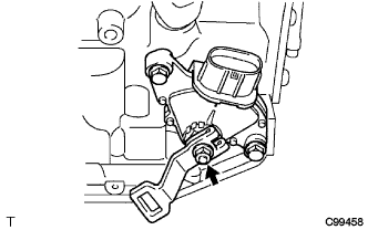
| 2. INSTALL DIFFERENTIAL GEAR LUBE APPLY TUBE |
Install the differential gear lube apply tube and transaxle apply tube clamp to the transaxle housing with the bolt.
- Torque:
- 9.8 N*m{100 kgf*cm, 87 in.*lbf}
- NOTICE:
- Make sure to insert the pipe to the stopper.
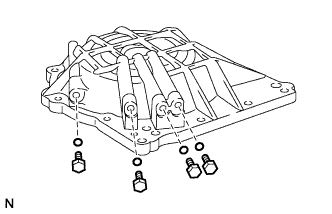
| 3. INSTALL NO. 1 TRANSAXLE CASE PLUG |
Install 2 new O-rings to the 2 No. 1 transaxle case plugs.
Install the 2 No. 1 transaxle case plugs to the rear transaxle cover.
- Torque:
- 7.4 N*m{76 kgf*cm, 66 in.*lbf}
| 4. INSTALL UNDERDRIVE OUTPUT SHAFT OIL SEAL RING |
Coat a new oil seal ring with ATF and install it to the transaxle housing.
| 5. INSTALL UNDERDRIVE CYLINDRICAL ROLLER BEARING |
Coat the underdrive cylindrical roller bearing with ATF.
Using SST and a press, install the underdrive cylindrical roller bearing.
- SST
- 09950-60020(09951-00810)
09950-70010(09951-07100)
- NOTICE:
- Do not apply excessive pressure to the bearing.
| 6. INSTALL UNDERDRIVE CLUTCH DRUM OIL SEAL RING |
Coat 2 new underdrive clutch drum oil seal rings with ATF, and install them to the rear transaxle cover.
- NOTICE:
- Do not expand the end gap of the oil seal ring too much.
- Secure the hooks firmly. Confirm that the oil seal ring rotates freely in its groove.
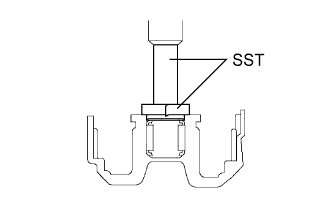
| 7. INSTALL NEEDLE ROLLER BEARING |
Wrap vinyl tape around SST 4.0 mm (0.157 in.) from the bottom of SST until the thickness of the tape is about 5.0 mm (0.197 in.).
- SST
- 09950-60010(09951-00320)
09950-70010(09951-07100)
- NOTICE:
- Clean SST to remove deposited oil before wrapping vinyl tape.
Coat the needle roller bearing with ATF.
Using SST and a press, install the needle-roller bearing to the transaxle case.
- SST
- 09950-60010(09951-00320)
09950-70010(09951-07100)
- NOTICE:
- Stop the press when the wrapped vinyl tape contacts the transaxle case.
| 8. INSTALL UNDERDRIVE BRAKE PISTON |
Coat 2 new O-rings with ATF, and install them to the underdrive brake piston.
- NOTICE:
- Make sure that the O-rings are not twisted or pinched when they are installed.
- Apply sufficient ATF to the O-rings before installation.
Coat the underdrive brake piston with ATF.
Install the underdrive brake piston to the transaxle case.
- NOTICE:
- Be careful not to damage the O-rings.
| 9. INSTALL UNDERDRIVE BRAKE RETURN SPRING SUB-ASSEMBLY |
Place SST on the return spring and compress the return spring with a press.
- SST
- 09387-00020
- NOTICE:
- Stop the press when the spring seat is lowered to a position 1 to 2 mm (0.039 to 0.078 in.) from the snap ring groove to prevent the spring seat from being deformed.
- After installing the return spring, check that all of the springs fit in the piston correctly.
Using a snap ring expander, press in the snap ring to the transaxle case.
- NOTICE:
- The snap ring must be fully engaged in the groove of the transaxle case.
| 10. INSTALL NO. 2 BREATHER PLUG |
| 11. INSTALL COUNTER DRIVE GEAR BEARING |
Coat the counter drive gear bearing with ATF.
Using SST and a press, install the bearing outer race.
- SST
- 09950-60020(09951-01030)
09950-70010(09951-07150)
09649-17010
- NOTICE:
- Do not apply excessive pressure to the bearing.
- Press-fit the bearing outer race until it contacts the transaxle case.
Using a snap ring expander, install the snap ring.
- NOTICE:
- The white mark on the snap ring should face upward.
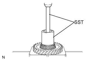
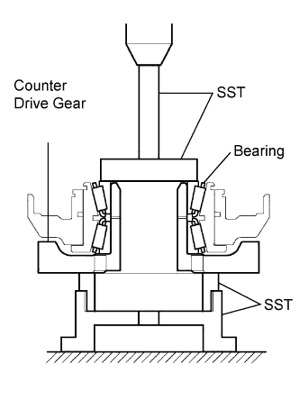
| 12. INSTALL COUNTER DRIVE GEAR |
Coat the counter drive gear with ATF.
Using SST and a press, install the tapered roller bearing to the counter drive gear.
- SST
- 09950-70010(09951-07150)
09649-17010
- NOTICE:
- Do not apply excessive pressure to the bearing.
Using SST and a press, press in the counter drive gear and bearing to the transaxle case.
- SST
- 09950-70010(09951-07150)
09223-15030
09527-17011
09950-60020(09951-00750)
- NOTICE:
- Do not apply excessive pressure to the counter drive gear.
| 13. INSTALL 1ST AND REVERSE BRAKE PISTON |
Coat 2 new O-rings with ATF.
Install the 2 O-rings to the 1st and reverse brake piston.
- NOTICE:
- Make sure that the O-rings are not twisted or pinched when they are installed.
- Apply sufficient ATF to the O-rings before installation.
Coat the 1st and reverse brake piston with ATF, and install it to the transaxle case.
- NOTICE:
- Be careful not to damage the O-rings.
| 14. INSTALL 1ST AND REVERSE BRAKE RETURN SPRING SUB-ASSEMBLY |
Place SST on the return spring and compress the return spring with a press.
- SST
- 09387-00070
- NOTICE:
- Stop the press when the spring seat is lowered to a position 1 to 2 mm (0.039 to 0.078 in.) from the snap ring groove to prevent the spring seat from being deformed.
- After installing the return spring, check that all of the springs fit in the piston correctly.
Using a snap ring expander, install the snap ring to the transaxle case.
- NOTICE:
- The snap ring must be fully engaged in the groove of the transaxle case.
- Secure the snap ring to the inside of the claw of the spring seat firmly.
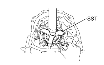
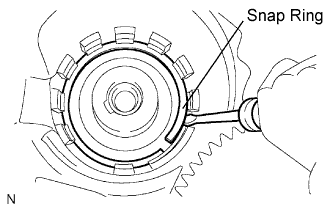
| 15. INSTALL FRONT PLANETARY RING GEAR |
Using a screwdriver, install the front planetary ring gear and snap ring to the brake hub.
- NOTICE:
- Confirm that the snap ring is engaged in the groove of the brake hub correctly.
| 16. INSTALL FRONT PLANETARY GEAR ASSEMBLY |
Install the front planetary gear assembly to the brake hub.
Using SST and a press, press-fit the front planetary gear assembly.
- SST
- 09950-60010(09951-00500)
09950-70010(09951-07100)
- NOTICE:
- Do not apply excessive pressure to the planetary gear assembly.
- Press the inner race of the LH tapered roller bearing, counter gear and front planetary gear assembly to the position where no preload should be applied to one pair of the tapered roller bearings (left and right).
Install a new washer as shown in the illustration.
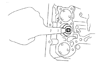
Using SST, install the nut.
- SST
- 09387-00030
09387-00080
- Torque:
- 280 N*m{2855 kgf*cm, 207 ft.*lbf}
- NOTICE:
- Install the washer after press-fitting each part, and then tighten the nut to the standard torque.
Using SST and a torque wrench, measure the turning torque of the bearing while rotating SST at 60 rpm. When the measured value is not as specified, gradually tighten the nut until it reaches the specified value.
- SST
- 09387-00080
- Standard turning torque at 60 rpm:
- 0.51 to 1.02 N*m (5.1 to 10.0 kgf*cm, 4.4 to 8.7 in.*lbf) for a new bearing
0.26 to 0.51 N*m (2.7 to 5.2 kgf*cm, 2.3 to 4.5 in.*lbf) for a used bearing
Tighten the nut gradually until the specified turning torque of the tapered roller bearing is measured.
- Torque:
- 350 N*m{3569 kgf*cm, 258 ft.*lbf}
Using a chisel and hammer, stake the front lock washer.
| 17. INSTALL INPUT SUN GEAR |
Coat the 2 thrust bearings with ATF.
Install the 2 thrust bearings, the bearing race and the input sun gear to the front planetary gear assembly.
- NOTICE:
- Install the bearing race on the side of the front planetary carrier. Make sure that the race is installed in the correct direction.
- When installing the thrust bearing and front sun gears, make sure that they are installed in the correct direction.
- Install the bearing race on the side of the front sun gear. Make sure that the race is installed in the correct direction.
- Install the thrust bearing and the race after holding the parts on the input sun gear by applying grease. Make sure that the assembling order is correct.
- Standard thrust bearing and bearing race diameter:
Item
| Inside
| Outside
|
Thrust Bearing A
| 32.5 mm (1.28 in.)
| 56.5 mm (2.224 in.)
|
Thrust Bearing C
| 38.6 mm (1.520 in.)
| 59.7 mm (2.35 in.)
|
Bearing Race B
| 40.2 mm (1.583 in.)
| 59.3 mm (2.335 in.)
|
Bearing Race D
| 38.6 mm (1.520 in.)
| 59.3 mm (2.335 in.)
|
| 18. INSTALL REAR PLANETARY GEAR ASSEMBLY |
Install the rear planetary gear assembly to the rear planetary ring gear.
Using a screwdriver, install the snap ring.
- NOTICE:
- Confirm that the snap ring is secured in the groove of the 1st and reverse brake hub correctly.
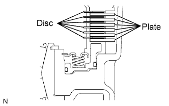
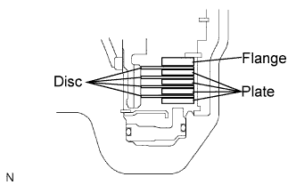
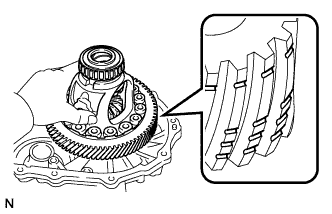
| 19. INSTALL 1ST AND REVERSE BRAKE CLUTCH DISC |
Coat the 6 discs with ATF.
Install the 6 plates and 6 discs.
- NOTICE:
- Make sure that the plates and discs are installed as shown in the illustration.
| 20. INSPECT PACK CLEARANCE OF FIRST AND REVERSE BRAKE |
Using a vernier caliper, measure the distance between the disc surface and the contact surface of the 2nd brake cylinder and transaxle case (Dimension A).
Select an appropriate flange so that the pack clearance will meet the specified value.
- Standard pack clearance:
- 1.16 to 1.35 mm (0.0457 to 0.0531 in.)
- HINT:
- Piston stroke = Dimension A - Flange thickness
- Standard flange thickness:
Mark
| Thickness
| Mark
| Thickness
|
1
| 1.8 mm (0.071 in.)
| 5
| 2.2 mm (0.087 in.)
|
2
| 1.9 mm (0.075 in.)
| 6
| 2.3 mm (0.091 in.)
|
3
| 2.0 mm (0.079 in.)
| 7
| 2.4 mm (0.094 in.)
|
4
| 2.1 mm (0.083 in.)
| 8
| 2.5 mm (0.098 in.)
|
Install the flange.
| 21. INSTALL 2ND BRAKE PISTON ASSEMBLY |
Install the 2nd brake piston to the transaxle case.
Install the snap ring and measure the inside diameter.
- Inside diameter:
- Greater than 167 mm (6.57 in.)
- NOTICE:
- Make sure that the tapered snap ring is installed in the correct direction.
- When the diameter does not meet the specified values, replace the snap ring with a new one.
- After installing the snap ring, confirm that there is no clearance between the 2nd brake cylinder and the fitting surface of the cylinder in the transaxle case.
| 22. INSTALL ONE-WAY CLUTCH SLEEVE OUTER |
Install the one-way clutch sleeve outer to the 2nd brake cylinder assembly.
- NOTICE:
- Make sure that the sleeve outer is installed in the correct direction.
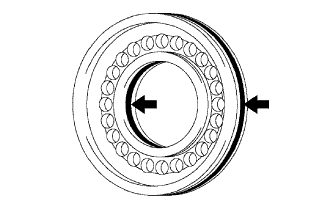
| 23. INSTALL ONE-WAY CLUTCH ASSEMBLY |
Install the one-way clutch inner race to the one-way clutch.
- NOTICE:
- Make sure that the inner race is installed in the correct direction.
- Confirm that the identification marks are visible.
Check that the one-way clutch locks when turned clockwise and rotates freely when turned counterclockwise as shown in the illustration.
- HINT:
- If the result is not as specified, replace the one-way clutch.
Install the one-way clutch and thrust needle roller bearing to the one-way clutch sleeve outer.
- Standard bearing diameter:
Item
| Inside
| Outside
|
Bearing
| 53.6 mm (2.110 in.)
| 69.4 mm (2.732 in.)
|
- NOTICE:
- Install the thrust bearing properly so that non-colored race can be seen.
| 24. INSTALL NO. 1 PLANETARY CARRIER THRUST WASHER |
Coat the No. 1 planetary carrier thrust washer with petroleum jelly, and install the washer onto the planetary sun gear assembly.
- NOTICE:
- After installing the washer, confirm that the projections of the washer are fitted firmly in the holes of the planetary sun gear assembly.
| 25. REMOVE REAR PLANETARY SUN GEAR ASSEMBLY |
Coat the No. 2 planetary carrier thrust washer with petroleum jelly, and install the washer onto the rear planetary sun gear.
Coat the bearing with petroleum jelly, and install the bearing onto the rear planetary sun gear.
- Standard bearing diameter:
Item
| Inside
| Outside
|
Race
| 33.0 mm (1.299 in.)
| 45.4 mm (1.787 in.)
|
Bearing
| 31.85 mm (1.254 in.)
| 45.2 mm (1.78 in.)
|
Install the rear planetary sun gear to the rear planetary gear.
- NOTICE:
- After installing the rear planetary sun gear, make sure that the B1 discs are engaged.
| 26. INSTALL 2ND BRAKE CLUTCH DISC |
Coat the 4 discs with ATF.
Install the 4 plates, 4 discs and flange to the transaxle case.
Temporarily install the snap ring.
| 27. INSPECT PACK CLEARANCE OF 2ND BRAKE |
Using a vernier caliper, measure the distance between the disc surface and snap ring surface (Dimension B).
Select an appropriate flange so that the pack clearance will meet the specified values.
- Standard clearance:
- 0.62 to 0.91 mm (0.0244 to 0.0358 in.)
- HINT:
- Piston stroke = Dimension B - Flange thickness - Snap ring thickness 1.6 mm (0.063 in.)
- Standard flange thickness:
Mark
| Thickness
| Mark
| Thickness
|
1
| 3.0 mm (0.118 in.)
| 5
| 3.4 mm (0.134 in.)
|
2
| 3.1 mm (0.122 in.)
| 6
| 3.5 mm (0.138 in.)
|
3
| 3.2 mm (0.126 in.)
| 7
| 3.6 mm (0.142 in.)
|
4
| 3.3 mm (0.130 in.)
| 8
| -
|
Temporarily remove the snap ring, attach the selected flange and reinstall the snap ring.
- NOTICE:
- Secure the snap ring so that the ends are visible through the groove of the transaxle case.
| 28. INSTALL OVERDRIVE DIRECT CLUTCH HUB SUB-ASSEMBLY |
Install the direct clutch hub to the planetary gear assembly.
- NOTICE:
- Be careful not to damage the bushing inside the overdrive direct clutch hub during installation.
Coat the thrust bearing with ATF.
Install the bearing race and the thrust bearing to the direct clutch hub.
- NOTICE:
- Be careful not to drop the bearing when it is installed.
- Standard bearing and race diameter:
Item
| Inside
| Outside
|
Bearing
| 24.7 mm (0.972 in.)
| 39.5 mm (1.555 in.)
|
Race
| 23.6 mm (0.929 in.)
| 38.0 mm (1.496 in.)
|
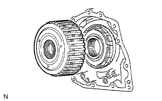
| 29. INSTALL DIRECT CLUTCH ASSEMBLY |
Coat the thrust bearing with ATF.
Install the direct clutch assembly and thrust bearing to the rear planetary sun gear assembly.
- NOTICE:
- The disc in the direct clutch should completely match with the hub attached outside the rear planetary sun gear. Otherwise, the rear cover cannot be installed.
Clean the connecting part of the transaxle case and the rear cover.
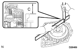
As shown in the illustration, place a straightedge on the direct clutch drum and measure the distance between the transaxle case and the straightedge using a vernier caliper (Dimension C).
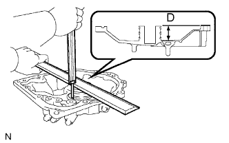
Using a vernier caliper and a straightedge, measure the dimension shown in the illustration (Dimension D).
Calculate the end play using the following formula. Select a thrust bearing which satisfies the specified end play and install the selected bearing.
- Standard end play:
- 0.244 to 0.901 mm (0.0096 to 0.0355 in.)
- NOTICE:
- Make sure that the non-colored race is facing the direct clutch.
- HINT:
- End play = Dimension D - Dimension C
- Standard bearing thickness and diameter:
Thickness
| Inside
| Outside
|
3.6 mm (0.1417 in.)
| 56.3 mm (2.217 in.)
| 75.7 mm (2.980 in.)
|
3.8 mm (0.1496 in.)
| 56.3 mm (2.217 in.)
| 75.7 mm (2.980 in.)
|
| 30. INSTALL NO. 1 GOVERNOR APPLY GASKET |
Install 3 new No. 1 governor apply gaskets to the transaxle case.
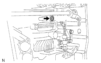
| 31. INSTALL BRAKE APPLY TUBE |
Install the clamp to the brake apply tube.
- NOTICE:
- Make sure to install the clamp to the apply tube before installing the apply tube to the transaxle case. This prevents the apply tube from being deformed or damaged.
Install the clutch apply tube.
Install the brake apply tube to the transaxle case with the bolt.
- Torque:
- 5.4 N*m{55 kgf*cm, 48 in.*lbf}
- NOTICE:
- The tube should be securely inserted until it reaches the stopper.
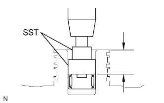
| 32. INSTALL NEEDLE ROLLER BEARING |
Using SST and a press, press the needle roller bearing into the rear transaxle cover.
- SST
- 09950-60010(09951-00230,09952-06010)
- Standard depth:
- 20.55 to 21.25 mm (0.8091 to 0.8366 in.)
- NOTICE:
- The engraved mark on the bearing should face upward.
- Continue pressing until the specified value is obtained.
Coat the needle roller bearing with ATF.
| 33. INSTALL REAR CLUTCH OIL SEAL RING OUTER |
Coat 3 new rear clutch oil seal rings with ATF, and install them to the rear transaxle cover.
- NOTICE:
- The oil seal rings should be fully engaged in the groove of the drum.
| 34. INSTALL NO. 1 TRANSAXLE CASE PLUG |
Coat 4 new O-rings with ATF.
Install the 4 O-rings to the 4 No. 1 transaxle case plugs.
Install the 4 No. 1 transaxle case plugs to the rear transaxle cover.
- Torque:
- 7.4 N*m{76 kgf*cm, 66 in.*lbf}
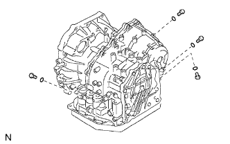
| 35. INSTALL REAR TRANSAXLE COVER SUB-ASSEMBLY |
Remove any packing material and be careful not to spill oil on the contact surface of the rear transaxle cover or the transaxle case.
Apply seal packing to the cover.
- Seal packing:
- Toyota Genuine Seal Packing 1281,
Three Bond 1281 or equivalent
- NOTICE:
- Make sure that seal packing is applied in a bead (section diameter: φ1.2 mm (0.047 in.)) so that the entire sealing surface will be evenly sealed. The seal packing should also protrude slightly from the flange after the cover is installed.
Apply adhesive to the threads of bolt A.
- Adhesive:
- Toyota Genuine Adhesive 1344,
Three Bond 1344 or equivalent
Install the 11 bolts.
- Torque:
- Bolt A:
- 19 N*m{194 kgf*cm, 14 ft.*lbf}
- Other bolts:
- 25 N*m{255 kgf*cm, 18 ft.*lbf}
| 36. INSTALL NO. 2 UNDERDRIVE CLUTCH DISC |
Coat the 4 discs with ATF.
Install the 4 discs, 4 plates and flange to the transaxle case.
- NOTICE:
- Make sure that discs, plates, and flange are installed in the correct order.
Using a screwdriver, install the snap ring.
- NOTICE:
- The snap ring should be fully engaged in the groove of the drum.
| 37. INSPECT PACK CLEARANCE OF UNDERDRIVE BRAKE |
Using a dial indicator, measure the underdrive brake pack clearance while applying and releasing compressed air (392 kPa, 4.0 kgf/cm2, 57 psi).
- Standard pack clearance:
- 1.81 to 2.20 mm (0.0713 to 0.0866 in.)
- HINT:
- Select an appropriate flange from the table below so that it will meet the specified values.
- Standard flange thickness:
Mark
| Thickness
| Mark
| Thickness
|
1
| 3.0 mm (0.118 in.)
| 4
| 3.1 mm (0.122 in.)
|
2
| 3.2 mm (0.126 in.)
| 5
| 3.3 mm (0.130 in.)
|
3
| 3.4 mm (0.134 in.)
| -
| -
|
Temporarily remove the snap ring, and attach the selected flange.
Reinstall the snap ring.
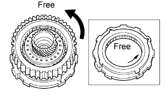
| 38. INSPECT UNDERDRIVE ONE-WAY CLUTCH ASSEMBLY |
Install the underdrive clutch assembly to the one-way clutch.
Check that the underdrive one-way clutch assembly locks when turned clockwise and rotates freely when turned counterclockwise as shown in the illustration.
If the result is not as specified, replace the underdrive one-way clutch.
| 39. INSTALL UNDERDRIVE ONE-WAY CLUTCH ASSEMBLY |
Install the outer race retainer to the one-way clutch.
- NOTICE:
- Secure the outer race retainer to the external tooth of the one-way clutch firmly.
Install the one-way clutch to the transaxle case.
- NOTICE:
- Make sure that the marks on the one-way clutch outer race can be seen.
Using a screwdriver, install the snap ring to the transaxle case.
- NOTICE:
- The snap ring should be fully engaged in the groove of the transaxle case.
| 40. INSTALL UNDERDRIVE CLUTCH ASSEMBLY |
Coat the bearing and bearing race with petroleum jelly, and install them onto the underdrive clutch.
- Standard bearing and bearing race diameter:
Item
| Inside
| Outside
|
Bearing
| 37.73 mm (1.4854 in.)
| 58.0 mm (2.2835 in.)
|
Race
| 29.9 mm (1.1772 in.)
| 55.5 mm (2.185 in.)
|
Install the underdrive clutch to the transaxle case.
- NOTICE:
- Do not damage the oil seal when installing the underdrive clutch drum sub-assembly.
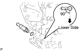
| 41. INSTALL PARKING LOCK PAWL |
Install the pawl pin and spring to the parking lock pawl.
Temporarily install the parking lock pawl, shaft and spring to the transaxle case as shown in the illustration.
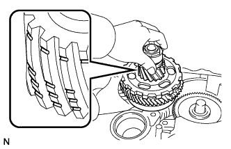
| 42. INSTALL UNDERDRIVE PLANETARY GEAR ASSEMBLY |
Install the underdrive planetary gear assembly to the transaxle case.
- NOTICE:
- Fully engage all the discs of the underdrive clutch and hub splines of the underdrive planetary gear assembly and install them securely.
- Check the number and position of the gear teeth.
Install the parking lock pawl shaft.
Install the pawl shaft clamp with the bolt.
- Torque:
- 9.8 N*m{100 kgf*cm, 87 in.*lbf}
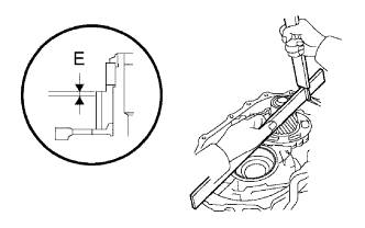
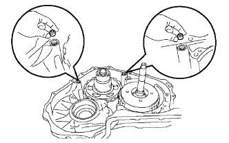
Using a straightedge and a vernier caliper as shown in the illustration, measure the gap between the top of the differential drive pinion in the underdrive planetary gear and the contact surface of the transaxle case and housing (Dimension E).
- NOTICE:
- Record dimension E for the following step.
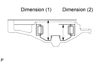
As shown in the illustration, measure the 2 places of the transaxle housing, and calculate dimension F using the formula below.
- NOTICE:
- Record dimension F for the following step.
- HINT:
- Dimension F = Dimension (1) - Dimension (2)
| 43. INSTALL MULTIPLE DISC CLUTCH HUB |
Install the No. 1 thrust bearing race to the transaxle case while checking its direction.
- Standard bearing race diameter:
Item
| Inside
| Outside
|
Bearing race
| 39.5 mm (1.555 in.)
| 45.8 mm (1.803 in.)
|
Coat the thrust needle roller bearing and race with petroleum jelly, and install them onto the multiple disc clutch hub.
- Standard thrust bearing and race diameter:
Item
| Inside
| Outside
|
Thrust bearing
| 36.4 mm (1.433 in.)
| 52.2 mm (2.055 in.)
|
Coat the needle roller bearing with ATF.
Install the needle roller bearing to the multiple clutch hub.
- Standard bearing diameter:
Item
| Inside
| Outside
|
Bearing
| 23.6 mm (0.929 in.)
| 44 mm (1.732 in.)
|
Install the multiple clutch hub to the transaxle case.
| 44. INSTALL FORWARD CLUTCH ASSEMBLY |
Coat the thrust needle roller bearing with ATF.
Install the thrust needle roller bearing to the forward clutch.
- Standard thrust bearing diameter:
Item
| Inside
| Outside
|
Thrust bearing
| 33.58 mm (1.3220 in.)
| 51.9 mm (2.043 in.)
|
- NOTICE:
- Install the thrust bearing properly so that the non-colored race or blue-colored race will be visible.
Install the forward clutch assembly to the transaxle case.
- NOTICE:
- Align the splines of all discs in the forward clutch with those of the multiple clutch hub to install them securely.
- Be careful not to damage the bushing inside of the forward clutch hub during installation.
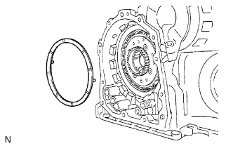
| 45. INSTALL OVERDRIVE BRAKE GASKET |
Install 2 new overdrive brake gaskets.
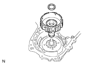
| 46. INSTALL DIFFERENTIAL GEAR ASSEMBLY |
Install the differential gear assembly to the transaxle case.
- NOTICE:
- Check the position and number of the grooves on each end face of the differential ring gear.
| 47. INSTALL NO. 2 THRUST BEARING UNDERDRIVE RACE |
Install the No. 2 thrust bearing underdrive race to the underdrive planetary gear assembly.
| 48. INSTALL THRUST NEEDLE ROLLER BEARING |
Coat the thrust needle roller bearing with ATF.
Calculate the end play using the following formula and dimensions E and F that were measured when installing the cylindrical roller bearing and underdrive planetary gear. Select an appropriate underdrive planetary gear thrust bearing race which satisfies the specified end play, and install the selected bearing race.
- Standard end play:
- 0.498 to 0.993 mm (0.01961 to 0.03909 in.)
- HINT:
- End play = Dimension F - Dimension E - Thrust bearing thickness 2.5 mm (0.0984 in.) - Underdrive thrust bearing race thickness
- Standard race thickness:
F - E
| Thickness
|
Less than 7.72 mm (0.3039 in.)
| 3.5 mm (0.138 in.)
|
7.72 mm (0.3039 in.)
| 3.8 mm (0.150 in.)
|
- Standard bearing and bearing race diameter:
Item
| Inside
| Outside
|
Bearing
| 57.2 mm (2.252 in.)
| 84.96 mm (3.345 in.)
|
Bearing race
| 56.4 mm (2.22 in.)
| 83 mm (3.268 in.)
|
| 49. INSTALL OIL PUMP ASSEMBLY |
Install the oil pump to the transaxle case with the 7 bolts.
- Torque:
- 22 N*m{225 kgf*cm, 16 ft.*lbf}
Coat the O-ring of the oil pump with ATF.
- NOTICE:
- Confirm that the input shaft rotates smoothly by hand after installing the oil pump.
| 50. INSTALL TRANSAXLE HOUSING |
Remove any packing material and be careful not to spill oil on the contact surface of the transaxle case or transaxle housing.
Apply seal packing to the transaxle case.
- Seal packing:
- Toyota Genuine Seal Packing 1281,
Three Bond 1281 or equivalent
Apply adhesive or equivalent to bolts A and D.
- Adhesive:
- Toyota Genuine Adhesive 1344,
Three Bond 1344 or equivalent
Install the transaxle housing and 16 bolts to the transaxle case.
- Torque:
- Bolt A:
- 22 N*m{224 kgf*cm, 16 ft.*lbf}
- Bolt B:
- 29 N*m{296 kgf*cm, 21 ft.*lbf}
- Bolt C:
- 29 N*m{296 kgf*cm, 21 ft.*lbf}
- Bolt D:
- 22 N*m{224 kgf*cm, 16 ft.*lbf}
- HINT:
- Each bolt length is indicated below.
- Bolt length:
- Bolt A:
- 50 mm (1.97 in.)
- Bolt B:
- 50 mm (1.97 in.)
- Bolt C:
- 42 mm (1.65 in.)
- Bolt D:
- 72 mm (2.84 in.)
- NOTICE:
- Tighten the bolts within 10 minutes of adhesive application.
- HINT:
- Bolt A is a non-reusable bolt. However, bolt A can be used after cleaning it.
| 51. INSPECT INPUT SHAFT END PLAY |
Using a dial indicator, measure the input shaft end play.
- Standard end play:
- 0.262 to 1.249 mm (0.0100 to 0.0494 in.)
| 52. SECURE AUTOMATIC TRANSAXLE ASSEMBLY |
Secure the transaxle assembly on wooden blocks.
| 53. INSTALL MANUAL VALVE LEVER SHAFT OIL SEAL |
Coat a new oil seal with MP grease.
Install the manual valve lever shaft oil seal to the transaxle case.
- SST
- 09950-60010(09951-00230)
09950-70010(09951-07100)
- Standard depth:
- -0.5 to 0.5 mm (-0.020 to 0.020 in. )
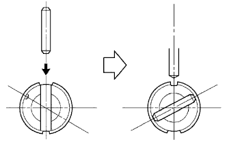
| 54. INSTALL PARKING LOCK ROD SUB-ASSEMBLY |
Install the parking lock rod to the manual valve lever.
| 55. INSTALL MANUAL VALVE LEVER SUB-ASSEMBLY |
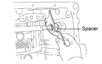
Install a new spacer and the manual valve lever shaft to the transaxle case.
- NOTICE:
- Do not damage the oil seal when installing the shaft to the transaxle case.
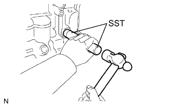
Using a pin punch and hammer, drive in a new pin.
Turn the spacer and lever shaft to align the small hole on the spacer with the staking position mark on the lever shaft.
Using a pin punch, stake the spacer through the small hole.
Check that the spacer does not turn.
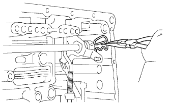
| 56. INSTALL MANUAL VALVE LEVER SHAFT RETAINER SPRING |
Using needle-nose pliers, install the retainer spring.
- NOTICE:
- Firmly install the spring to the shaft.
| 57. INSTALL PARKING LOCK PAWL BRACKET |
Install the parking lock pawl bracket with the 2 bolts.
- Torque:
- 20 N*m{204 kgf*cm, 15 ft.*lbf}
- HINT:
- The bolt length is indicated below.
- Bolt length:
- 25 mm (0.984 in.)
- NOTICE:
- Make sure that the parking rod is placed between the parking pawl and the guide of the parking bracket when the parking bracket is installed.
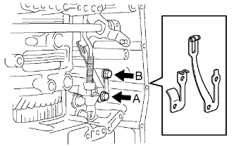
| 58. INSTALL MANUAL DETENT SPRING SUB-ASSEMBLY |
Install the manual detent spring sub-assembly and cover with the 2 bolts.
- NOTICE:
- Make sure to install the manual detent spring and cover in this order.
- HINT:
- Tighten bolt A first, and then bolt B.
- Torque:
- Bolt A:
- 20 N*m{204 kgf*cm, 15 ft.*lbf}
- Bolt B:
- 12 N*m{122 kgf*cm, 9 ft.*lbf}
- HINT:
- Each bolt length is indicated below.
- Bolt length:
- Bolt A:
- 27 mm (1.06 in.)
- Bolt B:
- 16 mm (0.63 in.)
| 59. INSTALL B-3 ACCUMULATOR PISTON |
Coat a new O-ring with ATF, and install it to the B-3 accumulator piston.
- NOTICE:
- Apply sufficient ATF before installing the O-ring.
- The O-ring must be installed in the correct position.
- Make sure that the O-ring is not twisted and that it does not protrude abnormally from the accumulator piston.
Install the accumulator piston to the transaxle case.
Coat the piston with ATF.
Install the 2 springs to the piston, and install the piston (with springs) to the transaxle case.
- NOTICE:
- Before installing the springs, check the identification color of each spring.
- Standard accumulator spring:
Spring
| Free length /
Outer diameter
| Identification Color
|
Inner
| 62.00 mm (2.4409 in.) /
15.50 mm (0.610 in.)
| Purple
|
Outer
| 74.23 mm (2.9224 in.) /
21.70 mm (0.854 in.)
|
| 60. INSTALL REVERSE CLUTCH ACCUMULATOR PISTON |
Coat 2 new O-rings with ATF, and install them to the reverse clutch accumulator piston.
- NOTICE:
- Apply sufficient ATF before installing the O-rings.
- The O-rings must be installed in the correct position.
- Make sure that the O-rings are not twisted and that they do not protrude abnormally from the accumulator piston.
Install the piston to the transaxle case.
Coat the accumulator piston with ATF.
Install the spring to the piston, and install the piston (with spring) to the transaxle case.
- NOTICE:
- Before installing the spring, check the identification color of the spring.
- Standard accumulator spring:
Free length
Outer diameter
| Identification Color
|
60.96 mm (2.3999 in.) /
14.10 mm (0.555 in.)
| Yellow
|
| 61. INSTALL C-3 ACCUMULATOR PISTON |
Coat a new O-ring with ATF, and install it to the C-3 accumulator piston.
- NOTICE:
- Apply sufficient ATF before installing the O-ring.
- The O-ring must be installed in the correct position.
- Make sure that the O-ring is not twisted and that it does not protrude abnormally from the accumulator piston.
Coat the piston with ATF, and install it to the transaxle case.
- NOTICE:
- Install the springs to each accumulator piston, checking the identification color of each spring.
- Standard accumulator spring:
Free length
Outer diameter
| Color
|
72.20 mm (2.8425 in.) /
19.0 mm (0.748 in.)
| Colorless
|
Install the spring to the C-3 accumulator piston.
- NOTICE:
- Install the springs to each accumulator piston, checking the identification color of each spring.
| 62. INSTALL CHECK BALL BODY |
Coat the check ball body with ATF.
Install the check ball body and spring.
- NOTICE:
- Be sure to place the spring in the hole in the check ball body. Make sure that they are installed in the correct direction.
| 63. INSTALL BRAKE DRUM GASKET |
Coat a new brake drum gasket with ATF, and install it to the transaxle case.
- NOTICE:
- Be sure not to damage the lip of the brake drum gasket when inserting the gasket to the case.
- Apply sufficient ATF to the gasket before installation.
- Make sure that the gasket is installed in the correct direction.
| 64. INSTALL TRANSAXLE CASE 2ND BRAKE GASKET |
Coat a new transaxle case 2nd brake gasket with ATF, and install it to the transaxle case.
- NOTICE:
- Be sure not to damage the lip of the transaxle case 2nd brake gasket when inserting the gasket to the case.
- Apply sufficient ATF to the gasket before installation.
- Make sure that the gasket is installed in the correct direction.
| 65. INSTALL NO. 1 GOVERNOR APPLY GASKET |
Coat a new No. 1 governor apply gasket with ATF, and install it to the transaxle case.
- NOTICE:
- Be sure not to damage the lip of the No. 1 governor apply gasket when inserting the gasket to the case.
- Apply sufficient ATF to the gasket before installation.
- Make sure that the gasket is installed in the correct direction.
| 66. INSTALL TRANSMISSION WIRE |
Coat a new O-ring with ATF, and install it to the transmission wire.
- NOTICE:
- Apply sufficient ATF to the O-ring before installation.
- Make sure that the O-ring is not twisted, protruded, or pinched when installing the transmission wire to the transaxle case.
Install the transmission wire retaining bolt.
- Torque:
- 5.4 N*m{55 kgf*cm, 48 in.*lbf}
| 67. CONNECT TRANSMISSION WIRE |
Coat the O-ring of the ATF temperature sensor with ATF.
Apply ATF to the bolt.
Install the ATF temperature sensor with the lock plate and bolt.
- Torque:
- 6.6 N*m{67 kgf*cm, 58 in.*lbf}
Connect the 7 solenoid valve connectors.
- HINT:
- Connect connectors A, B, C, D, E, F, and G, in the order of shortest to longest.
| 68. INSTALL TRANSMISSION VALVE BODY ASSEMBLY |
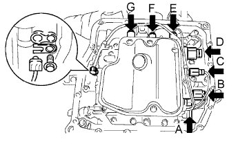
Apply ATF to the 17 bolts.
While positioning the manual valve lever, install the valve body to the transaxle case with the 17 bolts.
- Torque:
- 11 N*m{112 kgf*cm, 8 ft.*lbf}
- HINT:
- Each bolt length is indicated below.
- Bolt length:
- Bolt A:
- 25 mm (0.984 in.)
- Bolt B:
- 57 mm (2.244 in.)
- Bolt C:
- 41 mm (1.614 in.)
- NOTICE:
- Push the valve body against the accumulator piston spring and the check ball body to install the valve body.
- When installing the valve body to the transaxle case, do not hold the solenoids.
- Temporarily tighten the bolts marked with (1) in the illustration first because they are positioning bolts.
| 69. INSTALL VALVE BODY OIL STRAINER ASSEMBLY |
Coat a new O-ring with ATF and install it to the oil strainer.
- NOTICE:
- Apply sufficient ATF to the O-ring before installation.
- Make sure that the O-ring is not twisted or pinched.
Install the oil strainer to the valve body with the 3 bolts.
- Torque:
- 11 N*m{112 kgf*cm, 8 ft.*lbf}
- NOTICE:
- Apply ATF to the bolts.
| 70. INSTALL AUTOMATIC TRANSAXLE OIL PAN SUB-ASSEMBLY |
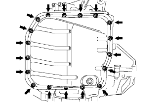
Install the 2 magnets to the oil pan.
Apply adhesive to 18 new bolts.
- Adhesive:
- Toyota Genuine Adhesive 1344, Three Bond 1344 or equivalent
Install the oil pan and a new oil pan gasket to the transaxle case with the 18 bolts.
- Torque:
- 7.6 N*m{77 kgf*cm, 67 in.*lbf}
- NOTICE:
- Apply adhesive to the bolts and tighten them within 10 minutes of application.
- Completely remove any oil or grease from the contact surfaces of the transaxle case and the oil pan with the gasket before installing the oil pan to the case.
| 71. INSTALL NO. 1 TRANSAXLE CASE PLUG |
Coat 4 new O-rings with ATF, and install them to the 4 No. 1 transaxle case plugs.
Install the 4 No. 1 transaxle case plugs to the transaxle case.
- Torque:
- 7.4 N*m{76 kgf*cm, 66 in.*lbf}
| 72. INSTALL SPEEDOMETER DRIVEN HOLE COVER SUB-ASSEMBLY |
Coat a new O-ring with ATF, and install it to the speedometer driven hole cover sub-assembly.
Install the speedometer driven hole cover sub-assembly with the bolt.
- Torque:
- 5.5 N*m{56 kgf*cm, 49 in.*lbf}
Coat 2 new O-rings with ATF and install them to the 2 speed sensors.
Install the 2 speed sensors to the transaxle case with the 2 bolts.
- Torque:
- 11 N*m{112 kgf*cm, 8 ft.*lbf}
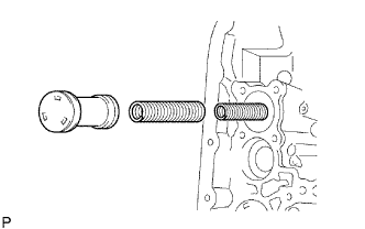
| 74. INSTALL OIL COOLER INLET TUBE ELBOW |
Coat a new O-ring with ATF, and install it to the elbow.
Install the elbow to the transaxle case.
- Torque:
- 27 N*m{275 kgf*cm, 20 ft.*lbf}
| 75. INSTALL OIL COOLER OUTLET TUBE ELBOW |
Coat a new O-ring with ATF, and install it to the elbow.
Install the elbow to the transaxle case.
- Torque:
- 27 N*m{275 kgf*cm, 20 ft.*lbf}
| 76. INSTALL BREATHER PLUG HOSE |
Install the breather plug hose to the transaxle case firmly.
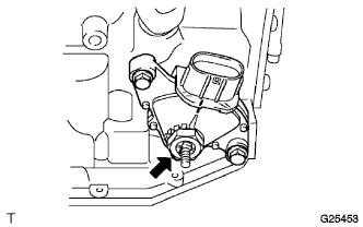
| 77. INSTALL PARK/NEUTRAL POSITION SWITCH ASSEMBLY |
Install the switch to the manual valve shaft.
Temporarily install the 2 bolts.
Install a new lock washer and tighten the manual valve shaft nut.
- Torque:
- 6.9 N*m{70 kgf*cm, 61 in.*lbf}
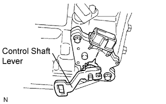
Temporarily install the control shaft lever.
Turn the lever counterclockwise until it stops, and then turn it clockwise 2 notches.
Remove the control shaft lever.
Align the groove with the neutral basic line.
Hold the switch in this position and tighten the 2 bolts.
- Torque:
- 6.9 N*m{70 kgf*cm, 61 in.*lbf}
Using a screwdriver, stake the nut with the lock washer.
Install the control shaft lever with the washer and nut.
- Torque:
- 13 N*m{133 kgf*cm, 10 ft.*lbf}