Dtc B2278 Engine Switch Circuit Malfunction
Engine. Toyota Rav4. Aca30, 33, 38 Gsa33 Zsa30, 35
DESCRIPTION
WIRING DIAGRAM
INSPECTION PROCEDURE
READ VALUE USING INTELLIGENT TESTER (START SWITCH 1 AND 2)
CHECK SWITCH CONDITION (ENGINE SWITCH)
INSPECT ENGINE SWITCH
CHECK HARNESS AND CONNECTOR (ENGINE SWITCH - MAIN BODY ECU AND BODY GROUND)
DTC B2278 Engine Switch Circuit Malfunction |
DESCRIPTION
This DTC is stored when 1) a malfunction is detected between the main body ECU and engine switch; or 2) either of the switches inside the engine switch is malfunctioning.DTC Code
| DTC Detection Condition
| Trouble Area
|
B2278
| Communication is abnormal between the main body ECU and engine switch or the engine switch is defective.
| - Main body ECU
- Engine switch
- Harness or connector
|
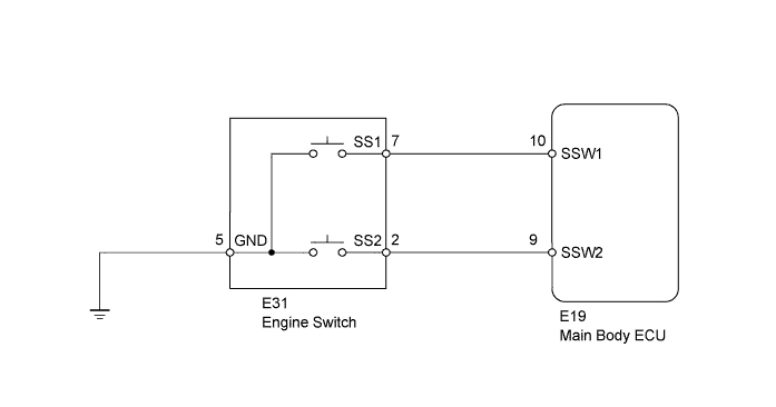
WIRING DIAGRAM
INSPECTION PROCEDURE
| 1.READ VALUE USING INTELLIGENT TESTER (START SWITCH 1 AND 2) |
Connect the intelligent tester to the DLC3.
Turn the engine switch on (IG) and turn the intelligent tester on.
Enter the following menus: Body / Main Body / Data List.
Read the value displayed on the intelligent tester.
Main BodyTester Display
| Measurement Item/Range
| Normal Condition
| Diagnostic Note
|
Start Switch1
| Start Switch 1/ON or OFF
| ON: Engine switch on (IG)
OFF: Engine switch off
| -
|
Start Switch2
| Start Switch 2/ON or OFF
| ON: Engine switch on (IG)
OFF: Engine switch off
| -
|
- OK:
- When the engine switch is turned on (IG), ON appears on the intelligent tester screen.
| 2.CHECK SWITCH CONDITION (ENGINE SWITCH) |
Make sure that the electrical key is inside the cabin.
With the shift lever in P, check that the power source mode changes as shown below each tine the engine switch is pushed.
- OK:
- off → on (ACC) → on (IG) → off
Remove the engine switch (RAV4_ACA30 RM0000020P000OX.html).
Measure the resistance according to the value(s) in the table below.
- Standard Resistance:
Tester Connection
| Switch Condition
| Specified Condition
|
7 (SS1) - 5 (GND)
| Pushed
| Below 1 Ω
|
2 (SS2) - 5 (GND)
| Pushed
| Below 1 Ω
|
7 (SS1) - 5 (GND)
| Not pushed
| 10 kΩ or higher
|
2 (SS2) - 5 (GND)
| Not pushed
| 10 kΩ or higher
|
| 4.CHECK HARNESS AND CONNECTOR (ENGINE SWITCH - MAIN BODY ECU AND BODY GROUND) |
Disconnect the E31 engine switch connector.
Disconnect the E19 main body ECU connector.
Measure the resistance according to the value(s) in the table below.
- Standard Resistance:
Tester Connection
| Condition
| Specified Condition
|
E31-7 (SS1) - E19-10 (SSW1)
| Always
| Below 1 Ω
|
E31-2 (SS2) - E19-9 (SSW2)
| Always
| Below 1 Ω
|
E31-5 (GND) - Body ground
| Always
| Below 1 Ω
|
E31-7 (SS1) or E19-10 (SSW1) - Body ground
| Always
| 10 kΩ or higher
|
E31-2 (SS2) or E19-9 (SSW2) - Body ground
| Always
| 10 kΩ or higher
|
| | REPAIR OR REPLACE HARNESS OR CONNECTOR |
|
|
| OK |
|
|
|
| REPLACE MAIN BODY ECU (INSTRUMENT PANEL JUNCTION BLOCK) |
|