Airbag System -- Diagnosis System |
| DESCRIPTION |
| CHECK DLC3 |
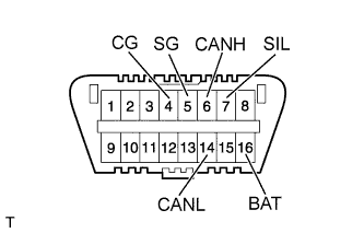
The ECU uses ISO 15765-4 for communication. The terminal arrangement of the DLC3 complies with ISO15031-3 and matches the ISO 15765-4 format.
Symbols (Terminal No.) Terminal Description Condition Specified Condition SIL (7) - SG (5) Bus + line During transmission Pulse generation CG (4) - Body ground Chassis ground Always Below 1 Ω SG (5) - Body ground Signal ground Always Below 1 Ω BAT (16) - Body ground Battery positive Always 11 to 14 V CANH (6) - CANL (14) HIGH-level CAN bus line Ignition switch off* 54 to 69 Ω CANH (6) - Battery positive HIGH-level CAN bus line Ignition switch off* 1 MΩ or higher CANH (6) - CG (4) HIGH-level CAN bus line Ignition switch off* 200 Ω or higher CANL (14) - Battery positive LOW-level CAN bus line Ignition switch off* 1 MΩ or higher CANL (14) - CG (4) LOW-level CAN bus line Ignition switch off* 200 Ω or higher - NOTICE:
- *: Before measuring the resistance, leave the vehicle as is for at least 1 minute and do not operate the ignition switch, any switches or doors.
- If the result is not as specified, the DLC3 may have a malfunction. Repair or replace the harness and connector.
- HINT:
- Connect the cable of the intelligent tester to the DLC3, turn the ignition switch on (IG) and attempt to use the tester. If the display indicates that a communication error has occurred, there is a problem either with the vehicle or with the tester.
- If communication is normal when the tester is connected to another vehicle, inspect the DLC3 on the original vehicle.
- If communication is still not possible when the tester is connected to another vehicle, the problem is probably in the tester itself. Consult the Service Department listed in the tester's instruction manual.
 |
| SYMPTOM SIMULATION |
- HINT:
- The most difficult case in troubleshooting is when no symptoms occur. In such cases, a thorough problem analysis must be carried out. A simulation of the same or similar conditions and environment in which the problem occurred in the customer's vehicle should be carried out. No matter how much skill or experience a technician has, troubleshooting without confirming the problem symptoms will lead to important repairs being overlooked and mistakes or delays.
- This leads to a standstill in troubleshooting.
Simulation method: When vibration seems to be the major cause
- HINT:
- Perform this method only during the primary check period (for approximately 6 seconds after the ignition switch is turned on (IG)).
Use your finger to slightly vibrate the part of the sensor considered to be the problem cause, and check whether the malfunction recurs.
- HINT:
- Wiggling the relays too strongly may result in open relays.
Gently wiggle the connector.
Slightly shake the wire harness vertically and horizontally.
The connector joint and fulcrum of the vibration are the major areas to be checked thoroughly.
 |
| FUNCTION OF SRS WARNING LIGHT |
Primary check
Turn the ignition switch off. Wait for at least 2 seconds, then turn the ignition switch on (IG). The SRS warning light comes on for approximately 6 seconds and the SRS airbag system diagnosis (including the seat belt pretensioner) is performed.
- HINT:
- If any malfunctions are detected during the primary check, the SRS warning light remains on even after the primary check period has elapsed.
Constant check
After the primary check, the center airbag sensor constantly monitors the SRS airbag system for trouble.
- HINT:
- If any malfunctions are detected during the constant check, the center airbag sensor functions as follows:
- The SRS warning light comes on.
- The SRS warning light goes off, and then comes on again. This blinking pattern indicates a source voltage drop. The SRS warning light goes off 10 seconds after the source voltage returns to normal.
Review
When the airbag system is normal:
The SRS warning light comes on only during the primary check period (for approximately 6 seconds after the ignition switch is turned on (IG)).When the airbag system malfunctions:
- The SRS warning light blinks after the primary check period has elapsed.
- The SRS warning light goes off after the primary check, but comes on again during the constant check.
- The SRS warning light remains off even after the ignition switch is turned from off to on (IG). However, if malfunctions such as an open circuit have occurred in the wire harness between the meter and ECU, the warning light comes on 10 seconds after the ignition switch is turned on (IG).
- HINT:
- The center airbag sensor keeps the SRS warning light on if any malfunctions have been detected in the airbag system.
- The SRS warning light blinks after the primary check period has elapsed.
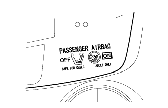
| FUNCTION OF PASSENGER AIRBAG ON/OFF INDICATOR (for Europe) |
Initial check
Turn the ignition switch on (IG).
The passenger airbag ON / OFF indicator comes on for approximately 4 seconds, then goes off for approximately 2 seconds.
Approximately 6 seconds after the ignition switch is turned on (IG), the passenger airbag ON /OFF indicator operates in accordance with the conditions listed below.
Airbag Cut-off Switch Position ON Indicator OFF Indicator ON ON OFF OFF OFF ON Switch failure OFF ON - HINT:
- The passenger airbag ON / OFF indicator operates as shown in the timing chart below in order to check the indicator light circuit.

 |
| SRS WARNING LIGHT CHECK |
Turn the ignition switch on (IG), and check that the SRS warning light comes on for approximately 6 seconds (primary check).
Check that the SRS warning light goes off approximately 6 seconds after the ignition switch is turned on (IG) (constant check).
- HINT:
- When any of the following symptoms occur, refer to the Problem Symptoms Table (RAV4_ACA30 RM000000XFA03UX.html).
- The SRS warning light comes on occasionally after the primary check period has elapsed.
- Even when the SRS warning light comes on, no DTCs are set.
- Even when the ignition switch is turned from off to on (IG), the SRS warning light remains off.
 |
| ACTIVATION PREVENTION MECHANISM |
FUNCTION OF ACTIVATION PREVENTION MECHANISM
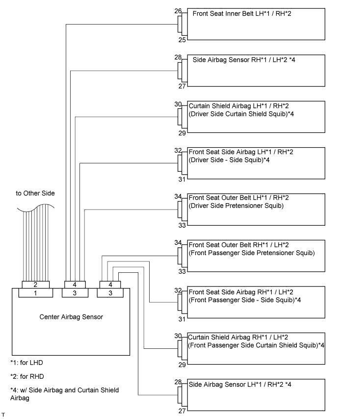
An activation prevention mechanism is built into the connector (on the center airbag sensor side) of the airbag system squib circuit to prevent accidental airbag activation.
This mechanism closes the circuit when the connector is disconnected by bringing the short spring into contact with the terminals and shutting off external electricity to prevent accidental airbag activation.
RELEASE METHOD OF ACTIVATION PREVENTION MECHANISM
To release the activation prevention mechanism, insert a piece of paper, with the same thickness as the male terminal (approximately 0.5 mm [0.020 in.]), between the terminals and the short spring to break the connection.
Refer to the illustrations below concerning connectors to utilize the activation prevention mechanism and its release method.
- CAUTION:
- Never release the activation prevention mechanism on the squib connector even when inspecting with the squib disconnected.
- NOTICE:
- Do not release the activation prevention mechanism unless specifically directed to do so by the troubleshooting procedure.
- To prevent the terminal and the short spring from being damaged, always use a piece of paper that is the same thickness as the male terminal.