READ VALUE USING INTELLIGENT TESTER (MASS AIR FLOW RATE)
CHECK MASS AIR FLOW METER (POWER SOURCE VOLTAGE)
CHECK HARNESS AND CONNECTOR (MASS AIR FLOW METER - ECM)
CHECK HARNESS AND CONNECTOR (MASS AIR FLOW METER - INTEGRATION RELAY)
CHECK HARNESS AND CONNECTOR (SENSOR GROUND)
CHECK HARNESS AND CONNECTOR (MASS AIR FLOW METER - ECM)
DTC P0100 Mass or Volume Air Flow Circuit |
DTC P0102 Mass or Volume Air Flow Circuit Low Input |
DTC P0103 Mass or Volume Air Flow Circuit High Input |
DESCRIPTION
The Mass Air Flow (MAF) meter is a sensor that measures the amount of air flowing through the throttle valve.The ECM uses this information to determine the fuel injection time and to provide the appropriate air-fuel ratio.
Inside the MAF meter, there is a heated platinum wire which is exposed to the flow of intake air.
By applying a specific electrical current to the wire, the ECM heats it to a given temperature. The flow of incoming air cools both the wire and an internal thermistor, affecting their resistance. To maintain a constant current value, the ECM varies the voltage applied to the wire and internal thermistor. The voltage level is proportional to the airflow through the sensor, and the ECM uses it to calculate the intake air volume.
The circuit is constructed so that the platinum hot wire and the temperature sensor create a bridge circuit, and the power transistor is controlled so that the potentials of A and B remain equal to maintain the predetermined temperature.
- HINT:
- When any of these DTCs are set, the ECM enters fail-safe mode. During fail-safe mode, the ignition timing is calculated by the ECM, according to the engine RPM and throttle valve position. Fail-safe mode continues until a pass condition is detected.

| DTC No. | DTC Detection Condition | Trouble Area |
| P0100 | MAF meter voltage less than 0.2 V, or more than 4.9 V for 3 seconds (1 trip detection logic) |
|
| P0102 | MAF meter voltage less than 0.2 V for 3 seconds (1 trip detection logic) |
|
| P0103 | MAF meter voltage more than 4.9 V for 3 seconds (1 trip detection logic) |
|
- HINT:
- When any of these DTCs are set, check the air-flow rate by selecting the following menu items on the intelligent tester: Powertrain / Engine and ECT / Data List / MAF.
| Mass Air Flow Rate (gm/s) | Malfunction |
| Approximately 0.0 |
|
| 271.0 or more |
|
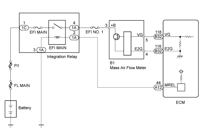
WIRING DIAGRAM
INSPECTION PROCEDURE
- HINT:
- Read freeze frame data using the intelligent tester. Freeze frame data records the engine condition when malfunctions are detected. When troubleshooting, freeze frame data can help determine if the vehicle was moving or stationary, if the engine was warmed up or not, if the air-fuel ratio was lean or rich, and other data from the time the malfunction occurred.
| 1.READ VALUE USING INTELLIGENT TESTER (MASS AIR FLOW RATE) |
Connect the intelligent tester to the DLC3.
Start the engine and turn the tester on.
Select the following menu items: Powertrain / Engine and ECT / Data List / MAF.
Read the values displayed on the tester.
- Result:
Mass Air Flow Rate (gm/s) Proceed to 0.0 A 271.0 or more B Between 1.0 and 270.0 (*1) C
|
| ||||
|
| ||||
| A | |
| 2.CHECK MASS AIR FLOW METER (POWER SOURCE VOLTAGE) |
 |
Disconnect the Mass Air Flow (MAF) meter connector.
Turn the ignition switch on (IG).
Measure the voltage according to the value(s) in the table below.
- Standard voltage:
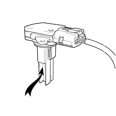
Tester Connection Switch Condition Specified Condition B1-3 (+B) - Body ground Ignition switch ON 11 to 14 V
Text in Illustration *a Front view of wire harness connector
(to Mass Air Flow Meter)
Reconnect the MAF meter connector.
|
| ||||
| OK | |
| 3.INSPECT MASS AIR FLOW METER |
 |
Perform On-vehicle Inspection (RAV4_ACA30 RM000001RYE012X.html).
Inspect the function of the mass air flow meter.
Remove the mass air flow meter with the connector connected.
Connect the intelligent tester to the DLC3.
Turn the ignition switch on (IG).
Turn the tester on.
Enter the following menus: Powertrain / Engine / Data List / MAF.
Blow air to the mass air flow meter and check that the intake air amount reading changes.
- OK:
- The reading changes.
|
| ||||
| OK | |
| 4.CHECK HARNESS AND CONNECTOR (MASS AIR FLOW METER - ECM) |
Disconnect the MAF meter connector.
Disconnect the ECM connector.
Measure the resistance according to the value(s) in the table below.
- Standard resistance (Check for open):
Tester Connection Condition Specified Condition B1-5 (VG) - B32-118 (VG) Always Below 1 Ω B1-4 (E2G) - B32-116 (E2G) Always Below 1 Ω
- Standard resistance (Check for short):
Tester Connection Condition Specified Condition B1-5 (VG) or B32-118 (VG) - Body ground Always 10 kΩ or higher
Reconnect the MAF meter connector.
Reconnect the ECM connector.
|
| ||||
| OK | ||
| ||
| 5.CHECK HARNESS AND CONNECTOR (MASS AIR FLOW METER - INTEGRATION RELAY) |
Disconnect the MAF meter connector.
Remove the integration relay from the engine room No. 1 relay block.
Measure the resistance according to the value(s) in the table below.
- Standard resistance (Check for open):
Tester Connection Condition Specified Condition B1-3 (+B) - 1A-4 Always Below 1 Ω
- Standard resistance (Check for short):
Tester Connection Condition Specified Condition B1-3 (+B) or 1A-4 - Body ground Always 10 kΩ or higher
Reconnect the MAF meter connector.
Reinstall the integration relay.
|
| ||||
| OK | ||
| ||
| 6.CHECK HARNESS AND CONNECTOR (SENSOR GROUND) |
Disconnect the MAF meter connector.
Measure the resistance according to the value(s) in the table below.
- Standard resistance:
Tester Connection Condition Specified Condition B1-4 (E2G) - Body ground Always Below 1 Ω
Reconnect the MAF meter connector.
|
| ||||
| NG | |
| 7.CHECK HARNESS AND CONNECTOR (MASS AIR FLOW METER - ECM) |
Disconnect the MAF meter connector.
Disconnect the ECM connector.
Measure the resistance according to the value(s) in the table below.
- Standard resistance (Check for open):
Tester Connection Condition Specified Condition B1-5 (VG) - B32-118 (VG) Always Below 1 Ω B1-4 (E2G) - B32-116 (E2G) Always Below 1 Ω
- Standard resistance (Check for short):
Tester Connection Condition Specified Condition B1-5 (VG) or B32-118 (VG) - Body ground Always 10 kΩ or higher
Reconnect the MAF meter connector.
Reconnect the ECM connector.
|
| ||||
| OK | ||
| ||