Oil Pump -- Removal |
| 1. DISCHARGE FUEL SYSTEM PRESSURE |
- CAUTION:
- The "DISCHARGE FUEL SYSTEM PRESSURE" procedures must be performed before disconnecting any part of the fuel system.
- After performing the "DISCHARGE FUEL SYSTEM PRESSURE" procedures, pressure will remain in the fuel lines. When disconnecting a fuel line, cover it with a shop rag or a piece of cloth to prevent fuel from spraying or coming out.
Remove the console box (RAV4_ACA30 RM000001RHJ00GX.html).
 |
Start the engine. After the engine has stopped, turn the ignition switch off.
- HINT:
- DTC P0171/P0172 (system too lean) may be set.
Check that the engine does not start.
Remove the fuel tank cap, and let the air out of the fuel tank.
Connect the connector.
|
Install the console box (RAV4_ACA30 RM000001RHG00HX.html).
| 2. DISCONNECT CABLE FROM NEGATIVE BATTERY TERMINAL |
| 3. REMOVE ENGINE ASSEMBLY |
Remove the engine from the vehicle (RAV4_ACA30 RM0000019Y9025X.html).
| 4. INSTALL ENGINE TO STAND |
Install the engine to an engine stand. Remove the sling device and chain block from the engine.
| 5. REMOVE NO. 2 OIL DIPSTICK GUIDE |
Remove the oil dipstick.
Remove the bolt and dipstick guide.
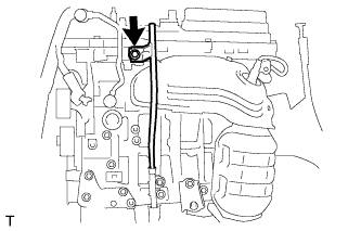 |
| 6. REMOVE OIL DIPSTICK GUIDE |
Remove the bolt and dipstick guide.
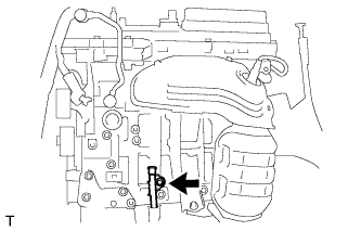 |
| 7. REMOVE OIL FILTER CAP ASSEMBLY |
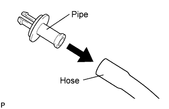
Connect the hose to a pipe.
- HINT:
- The drain pipe is supplied with the oil filter element.
 |
Remove the oil filter drain plug and O-ring, insert the drain pipe into the oil filter cap, and drain the engine oil into a container.
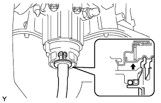 |
Make sure that oil is completely drained, and remove the pipe and O-ring.
- HINT:
- Be sure to turn the pipe in the direction indicated by the arrow to remove it.
 |
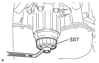
Using SST, remove the oil filter cap together with the oil filter element.
- SST
- 09228-06501
 |
| 8. REMOVE OIL FILTER ELEMENT |
Remove the oil filter element and 2 O-rings from the oil filter cap.
- NOTICE:
- Be sure to remove the O-ring (for the cap) by hand, without using any tools, to prevent damage to the groove for the O-ring on the cap.
 |
| 9. REMOVE NO. 2 OIL PAN SUB-ASSEMBLY |
Remove the 16 bolts and 2 nuts.
 |
Insert the blade of an oil pan seal cutter between the oil pans, cut through the applied sealer and remove the oil pan.
- NOTICE:
- Be careful not to damage the contact surfaces of the oil pans.
 |
| 10. REMOVE OIL STRAINER SUB-ASSEMBLY |
Remove the bolt, 2 nuts, oil strainer and gasket.
 |
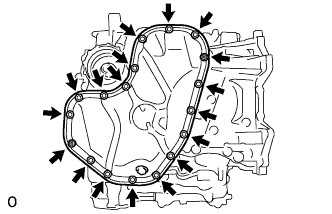
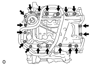
| 11. REMOVE OIL PAN SUB-ASSEMBLY |
Remove the 16 bolts and 2 nuts.
- HINT:
- Be sure to clean the bolts and stud bolts and check the threads for cracks or other damage.
 |
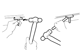
Remove the oil pan by prying between the oil pan and cylinder block with a screwdriver.
- NOTICE:
- Be careful not to damage the contact surfaces of the cylinder block and oil pan.
- HINT:
- Tape the screwdriver tip before use.
 |
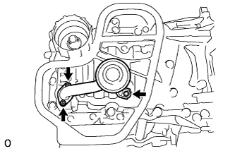
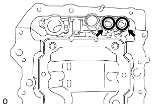
Remove the 2 O-rings from the oil pump.
 |
| 12. REMOVE WATER INLET HOUSING |
Remove the 2 nuts and remove the water inlet from the water inlet housing.
 |
| 13. REMOVE OIL PIPE |
Remove the bolt.
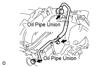 |
Remove the 2 oil pipe unions and oil pipe.
Remove the oil control valve filter RH and gaskets.
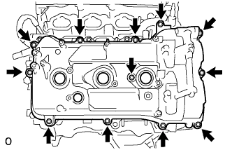
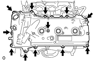
| 14. REMOVE CYLINDER HEAD COVER SUB-ASSEMBLY (for Bank 1) |
Remove the 12 bolts, cylinder head cover and gasket.
- HINT:
- Make sure the removed parts are returned to the same locations they were removed from.
 |
| 15. REMOVE NO. 1 OIL PIPE |
Remove the 2 oil pipe unions, gaskets and oil pipe.
 |
Remove the oil control valve filter LH and gaskets.
| 16. REMOVE CYLINDER HEAD COVER SUB-ASSEMBLY (for Bank 2) |
Remove the 12 bolts, cylinder head cover and gasket.
- HINT:
- Make sure the removed parts are returned to the same locations they were removed from.
 |
| 17. REMOVE CRANKSHAFT PULLEY |
Using SST, hold the crankshaft pulley and loosen the pulley bolt. Continue to loosen the bolt until only 2 or 3 threads are screwed into the crankshaft.
- SST
- 09213-70011(09213-70020)
09330-00021
 |
Using the pulley set bolt and SST, remove the crankshaft pulley and pulley bolt.
- SST
- 09950-50013(09951-05010,09952-05010,09953-05020,09954-05021)
 |
| 18. REMOVE TIMING CHAIN COVER SUB-ASSEMBLY |
Remove the 23 bolts and 2 nuts as shown in the illustration.
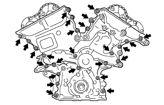 |
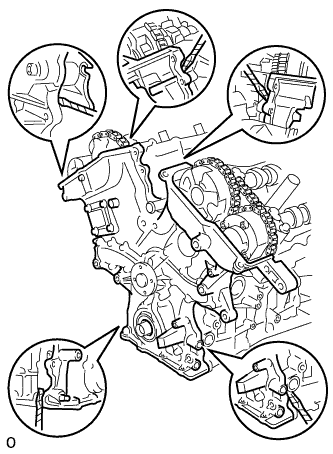
Remove the timing chain cover by prying between the timing chain cover and cylinder head or cylinder block with a screwdriver.
- HINT:
- Tape the screwdriver tip before use.
- NOTICE:
- Do not damage the contact surfaces of the cylinder head, cylinder block and timing chain cover.
 |
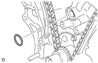
Remove the gasket.
 |