Brake Booster (For 2Gr-Fe Rhd) -- Installation |
| 1. INSTALL CHECK VALVE GROMMET |
Install the check valve grommet to the brake booster assembly.
| 2. INSTALL BRAKE VACUUM CHECK VALVE ASSEMBLY |
Install the brake vacuum check valve assembly to the brake booster assembly.
| 3. INSTALL BRAKE BOOSTER GASKET |
Install a new brake booster gasket to the brake booster assembly.
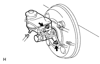
| 4. INSTALL BRAKE BOOSTER ASSEMBLY |
Tape the tip of the push rod of the brake booster assembly.
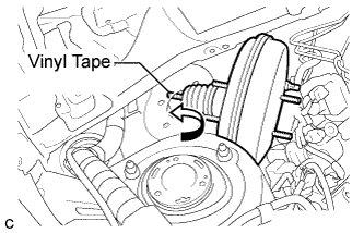 |
Install the brake booster assembly to the body by pushing the push rod as shown in the illustration.
- NOTICE:
- Do not damage the brake lines or clamps. If any parts are damaged, replace them with new ones.
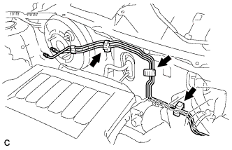
Engage the 3 clamps with the brake lines.
 |
| 5. INSTALL BRAKE MASTER CYLINDER PUSH ROD CLEVIS |
Temporarily install the lock nut and brake master cylinder push rod clevis to the brake booster assembly.
- HINT:
- Fully tighten the lock nut after adjusting the brake pedal height.
Completely install the brake booster assembly with the 4 nuts.
- Torque:
- 12.7 N*m{130 kgf*cm, 9 ft.*lbf}
 |
| 6. INSTALL NO. 1 HOSE TO HOSE TUBE |
Install the No. 1 hose to hose tube with the 2 nuts.
- Torque:
- 5.4 N*m{55 kgf*cm, 48 in.*lbf}
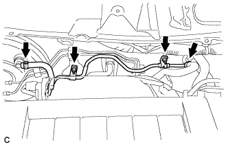 |
Slide the 2 clips and connect the No. 1 hose to hose tube.
| 7. INSTALL BRAKE MASTER CYLINDER SUB-ASSEMBLY |
- NOTICE:
- The master cylinder and piston are designed so that the piston can easily fall out. Prevent this by making sure to tip of the master cylinder points downward when handling the master cylinder.
- Make sure foreign matter does not attach to the master cylinder's piston. If foreign matter attaches, clean it off with a cloth. Then apply lithium soap base glycol grease to the entire outer circumference contact surface area of the piston.
Install a new O-ring to the master cylinder.
Install the master cylinder to the booster with the 2 nuts.
- Torque:
- 12.5 N*m{127 kgf*cm, 9 ft.*lbf}
 |
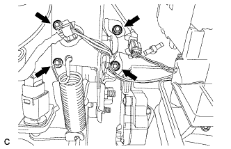
Using a union nut wrench, connect the 2 brake lines labeled C to the master cylinder.
- Torque:
- without union nut wrench:
- 15.2 N*m{155 kgf*cm, 11 ft.*lbf}
- with union nut wrench:
- 14 N*m{144 kgf*cm, 10 ft.*lbf}
- HINT:
- Use a torque wrench with a fulcrum length of 300 mm (11.8 in.).
- This torque value is effective when the union nut wrench is parallel to the torque wrench.
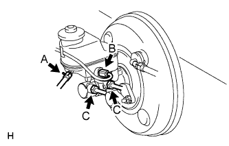 |
Connect the brake fluid level warning switch connector labeled B to the master cylinder.
for Manual Transaxle:
Connect the clutch reservoir tube labeled A to the master cylinder.
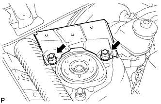
| 8. INSTALL COWL BODY MOUNTING REINFORCEMENT RH |
Install the cowl body mounting reinforcement RH with the 2 nuts.
- Torque:
- 50 N*m{510 kgf*cm, 37 ft.*lbf}
 |
| 9. INSTALL COWL TOP PANEL OUTER SUB-ASSEMBLY |
Install the cowl top panel outer sub-assembly with the 14 bolts.
- Torque:
- 7.5 N*m{76 kgf*cm, 66 in.*lbf}
- Torque:
- 7.5 N*m{76 kgf*cm}
 |
Connect the connector.
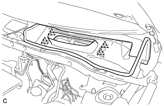
| 10. INSTALL COWL VENTILATOR HOUSING SUB-ASSEMBLY |
Engage the 4 clips to install the cowl ventilator housing sub-assembly.
 |
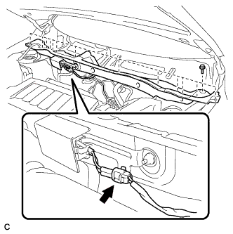
| 11. INSTALL WINDSHIELD WIPER MOTOR AND LINK ASSEMBLY |
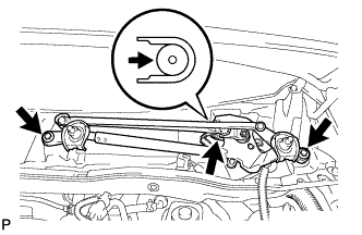 |
Connect the connector and attach the clamp.
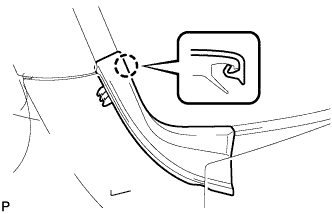
Move the wiper motor and link in the direction shown by the arrow in the illustration to attach the wiper cushion to the body, and install the wiper motor and link.
Install the 2 bolts.
- Torque:
- 5.5 N*m{56 kgf*cm, 49 in.*lbf}
| 12. INSTALL COWL TOP VENTILATOR LOUVER |
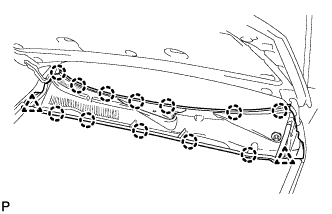 |
Attach the 12 claws and install the louver.
Install the 2 clips.
| 13. INSTALL FRONT FENDER TO COWL SIDE SEAL LH |
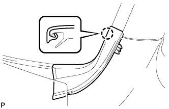 |
Attach the claw to install the front fender to cowl side seal.
| 14. INSTALL FRONT FENDER TO COWL SIDE SEAL RH |
 |
Attach the claw to install the front fender to cowl side seal.
| 15. INSTALL FRONT WIPER ARM AND BLADE ASSEMBLY RH |
Stop the wiper motor at the automatic stop position.
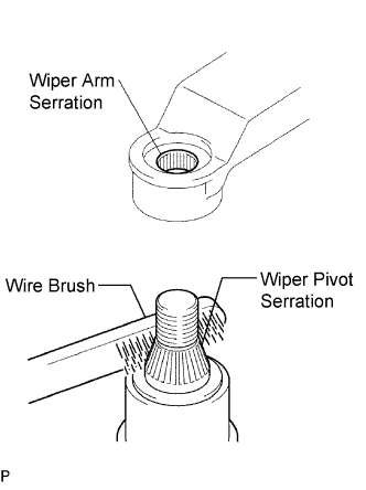 |
Clean the wiper arm serration with a round file or equivalent.
Clean the wiper pivot serration with a wire brush.
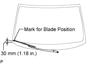
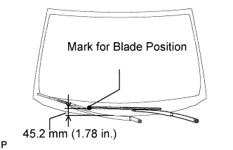
Install the arm and blade with the nut. Make sure that the arm and blade comes to the position shown in the illustration.
- Torque:
- 26 N*m{265 kgf*cm, 19 ft.*lbf}
- HINT:
- Hold down the arm hinge with your hand while tightening the nut.
 |
| 16. INSTALL FRONT WIPER ARM AND BLADE ASSEMBLY LH |
Clean the wiper arm serration with a round file or equivalent.
|
Clean the wiper pivot serration with a wire brush.
Install the arm and blade with the nut. Make sure that the arm and blade comes to the position shown in the illustration.
- Torque:
- 26 N*m{265 kgf*cm, 19 ft.*lbf}
- HINT:
- Hold down the arm hinge with your hand while tightening the nut.
 |
Operate the front wipers while spraying water or washer fluid on the windshield. Ensure that there is no interference between the blades and pillar.
| 17. INSTALL WINDSHIELD WIPER ARM COVER |
Install the 2 caps.
| 18. INSTALL PUSH ROD PIN |
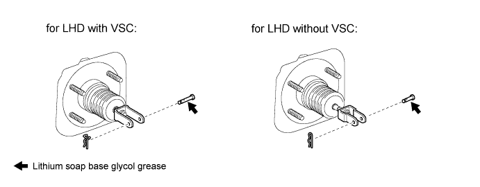
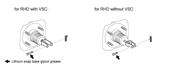
Apply lithium soap base glycol grease to the push rod pin.
Install the push rod pin to the push rod clevis.
- NOTICE:
- The push rod pin must be installed as shown in the illustration.
Install a new clip to the push rod pin.
- NOTICE:
- The clip must be installed as shown in the illustration.
| 19. FILL RESERVOIR WITH BRAKE FLUID |
- Fluid:
- SAE J1703 or FMVSS No. 116 DOT3
- NOTICE:
- Make sure there is sufficient brake fluid in the can.
- After adding braking fluid, make sure the reservoir is sufficiently full.
| 20. BLEED BRAKE MASTER CYLINDER |
- HINT:
- If the master cylinder has been disassembled or if the reservoir becomes empty, bleed air from the master cylinder.
Using a union nut wrench, disconnect the 2 brake lines from the master cylinder.
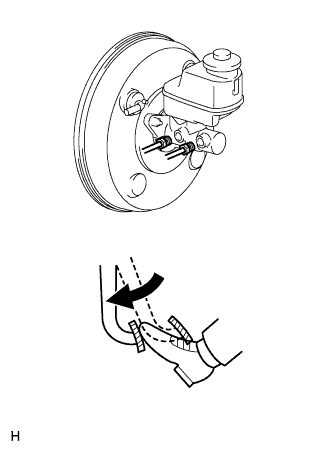 |
Slowly depress and hold the brake pedal.
Block the outer holes with your fingers, and release the pedal.
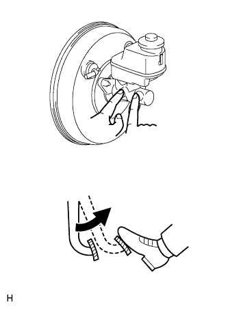 |
Repeat the 2 previous steps 3 or 4 times.
Using a union nut wrench, connect the 2 brake lines to the master cylinder.
- Torque:
- without union nut wrench:
- 15.2 N*m{155 kgf*cm, 11 ft.*lbf}
- with union nut wrench:
- 14 N*m{144 kgf*cm, 10 ft.*lbf}
- HINT:
- Use a torque wrench with a fulcrum length of 300 mm (11.8 in.).
- This torque value is effective when the union nut wrench is parallel to the torque wrench.
| 21. BLEED BRAKE LINE |
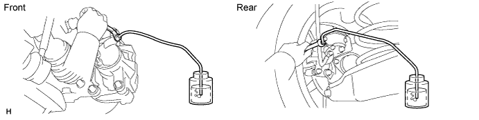
Remove the bleeder plug cap.
Connect the vinyl tube to the bleeder plugs.
Depress the brake pedal several times, and then loosen the bleeder plug with the pedal depressed.
When fluid stops coming out, immediately tighten the bleeder plug. Then release the pedal.
Repeat the 2 previous steps until all the air in the brake fluid is gone.
Tighten the bleeder plug.
- Torque:
- 8.3 N*m{85 kgf*cm, 73 in.*lbf}
Install the cap.
Bleed air from the brake line for each wheel by repeating the above procedures.
| 22. BLEED ABS AND TRACTION ACTUATOR |
- NOTICE:
- After bleeding the air from the brake system, if the height or feel of the brake pedal cannot be obtained, perform air bleeding of the brake actuator with an intelligent tester by following the procedure below.
Depress the brake pedal more than 20 times with the engine off.
Connect the intelligent tester to the DLC3, and turn the ignition switch on (IG).
- NOTICE:
- Do not start the engine.
Select AIR BLEEDING on the intelligent tester.
- HINT:
- Refer to the intelligent tester operator's manual for further details.
Bleed the air out of the suction line.
- NOTICE:
- Perform the bleeding at the right front wheel and right rear wheel.
- Bleed the air by following the steps displayed on the intelligent tester.
Connect a vinyl tube to the bleeder plug at the right front wheel or the right rear wheel.
Loosen the bleeder plug.
Operate the brake actuator to bleed the air using the intelligent tester.
- NOTICE:
- Release the brake pedal at this time.
- HINT:
- This operation stops automatically after 4 seconds.
Check if the operation has stopped by referring to the intelligent tester display.
Temporarily tighten the bleeder plug.
Repeat the 4 previous steps until all air in the fluid is completely bled out.
Tighten the bleeder plug.
- Torque:
- 8.3 N*m{85 kgf*cm, 73 in.*lbf}
Repeat all of the above procedures for the right rear wheel to bleed the air out of the suction line.
Bleed the air out of the pressure reduction line.
- NOTICE:
- Perform the bleeding at the 4 wheels.
- Bleed the air by following the steps displayed on the intelligent tester.
Connect a vinyl tube to either one of the bleeder plugs.
Loosen the bleeder plug.
Using the intelligent tester, operate the brake actuator assembly, completely depress the brake pedal and hold it there.
- NOTICE:
- During this procedure, the pedal will feel heavy, but completely depress it so that the brake fluid comes out of the bleeder plug.
- Hold the brake pedal depressed. Do not depress and release the pedal repeatedly.
- HINT:
- The operation stops automatically after 4 seconds. When performing this procedure continuously, set an interval of at least 20 seconds.
Tighten the bleeder plug, then release the brake pedal.
Repeat the 3 previous steps until all air in the fluid is completely bled out.
Tighten the bleeder plug.
- Torque:
- 8.3 N*m{85 kgf*cm, 73 in.*lbf}
Repeat all of the above procedures for the other wheels to bleed the air out of the pressure reduction line.
| 23. INSPECT BRAKE FLUID LEVEL IN RESERVOIR |
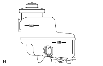 |
Check the fluid level and add fluid if necessary.
- Fluid:
- SAE J1703 or FMVSS No. 116 DOT3
- HINT:
- Add fluid to a level between the reservoir's MIN and MAX lines.
| 24. INSPECT FOR FLUID LEAK |