INSTALL TORQUE CONVERTER CLUTCH ASSEMBLY (for Automatic Transaxle)
INSTALL COOLER COMPRESSOR ASSEMBLY (w/ Air Conditioning System)
INSTALL CLUTCH RELEASE CYLINDER ASSEMBLY (for Manual Transaxle)
INSTALL TRANSAXLE CONTROL CABLE ASSEMBLY (for Manual Transaxle)
INSTALL TRANSAXLE CONTROL CABLE ASSEMBLY (for Automatic Transaxle)
Engine Assembly -- Installation |
| 1. INSTALL FLYWHEEL SUB-ASSEMBLY (for Manual Transaxle) |
Clean the 8 bolts and 8 bolt holes.
Apply adhesive to 2 or 3 threads of the 8 bolts.
- Adhesive:
- Toyota Genuine Adhesive 1324, Three Bond 1324 or Equivalent
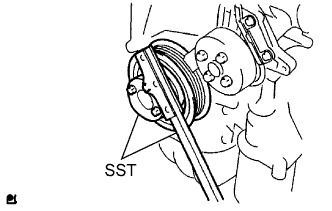
Using SST, hold the crankshaft.
- SST
- 09213-54015(91651-60855)
09330-00021
 |
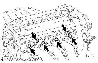
Using several steps, uniformly install and tighten the 8 bolts in the sequence shown in the illustration.
- Torque:
- 130 N*m{1,326 kgf*cm, 96 ft.*lbf}
 |
| 2. INSTALL CLUTCH DISC ASSEMBLY (for Manual Transaxle) |
 |
Insert SST in the disc, then insert them in the flywheel.
- SST
- 09301-00210
- NOTICE:
- Take care not to insert the clutch disc in the wrong direction.
| 3. INSTALL CLUTCH COVER ASSEMBLY (for Manual Transaxle) |
 |
Align the matchmarks on the cover and flywheel.
Following the procedures shown in the illustration, tighten the 6 bolts in order, starting with the bolt located near the knock pin on the top.
- Torque:
- 19 N*m{195 kgf*cm, 14 ft.*lbf}
- HINT:
- Following the order in the illustration, tighten the bolts one at a time, evenly.
- Move SST up and down, and right and left lightly after checking that the disc is in the center to tighten the bolts.
- SST
- 09301-00210
| 4. INSTALL MANUAL TRANSAXLE ASSEMBLY (for Manual Transaxle) |
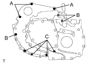 |
Align the input shaft with the clutch disc and install the transaxle to the engine.
Install the 10 bolts.
- Torque:
- 64 N*m{653 kgf*cm, 47 ft.*lbf}for bolt A
- 46 N*m{469 kgf*cm, 34 ft.*lbf}for bolt B
- 44 N*m{449 kgf*cm, 32 ft.*lbf}for bolt C
| 5. INSTALL STIFFENER PLATE RH (for Manual Transaxle) |
 |
Install the stiffener plate with the 4 bolts.
- Torque:
- 46 N*m{469 kgf*cm, 34 ft.*lbf}
| 6. INSTALL STIFFENER PLATE LH (for Manual Transaxle) |
 |
Install the stiffener plate with the 4 bolts.
- Torque:
- 46 N*m{469 kgf*cm, 34 ft.*lbf}
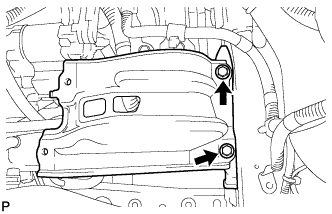
| 7. INSTALL FLYWHEEL HOUSING UNDER COVER (for Manual Transaxle) |
 |
Install the insulator with the 2 bolts.
- Torque:
- 9.0 N*m{92 kgf*cm, 80 in.*lbf}
| 8. INSTALL DRIVE PLATE SUB-ASSEMBLY (for Automatic Transaxle) |
Clean the 8 bolts and 8 bolt holes.
Apply adhesive to 2 or 3 threads of the 8 bolts.
- Adhesive:
- Toyota Genuine Adhesive 1324, Three Bond 1324 or Equivalent
Using SST, hold the crankshaft.
- SST
- 09213-54015(91651-60855)
09330-00021
|
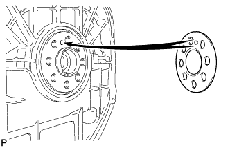
Install the front spacer.
- HINT:
- Align the pin of the front spacer with the pin hole of the crankshaft.
 |
Install the drive plate and rear spacer onto the crankshaft.
 |
Using several steps, uniformly install and tighten the 8 bolts in the sequence shown in the illustration.
- Torque:
- 98 N*m{1,000 kgf*cm, 72 ft.*lbf}
 |
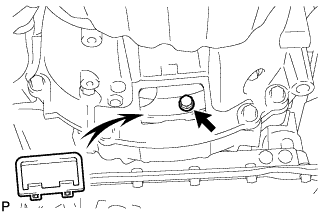
| 9. INSTALL TORQUE CONVERTER CLUTCH ASSEMBLY (for Automatic Transaxle) |
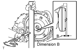
Install the torque converter clutch to the automatic transaxle.
Using a vernier caliper, measure dimension A between the transaxle and the end surface of the drive plate.
 |
Using a vernier caliper and straightedge, measure the dimension B shown in the illustration and check that B is greater than A.
- Standard dimension:
- A + 1.0 mm (0.039 in.) or more
 |
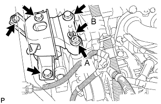
| 10. INSTALL AUTOMATIC TRANSAXLE ASSEMBLY |
 |
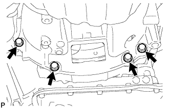
Install the automatic transaxle with the 5 upper side mounting bolts to the engine.
- Torque:
- 64 N*m{653 kgf*cm, 47 ft.*lbf} for bolt A
- 46 N*m{469 kgf*cm, 34 ft.*lbf} for bolt B
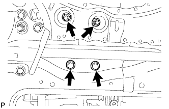
Install the 4 lower side mounting bolts.
- Torque:
- 37 N*m{377 kgf*cm, 27 ft.*lbf}
 |
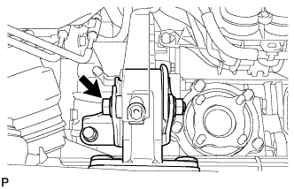
Install the 6 torque converter clutch mounting bolts.
- Torque:
- 41 N*m{418 kgf*cm, 30 ft.*lbf}
- HINT:
- First install the green colored bolt and then the 5 bolts.
 |
Install the flywheel housing under cover.
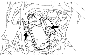
| 11. INSTALL STARTER ASSEMBLY |
Install the starter with the 2 bolts.
- Torque:
- 37 N*m{377 kgf*cm, 27 ft.*lbf}
 |
Connect the starter connector.
 |
Install the terminal nut and cover the nut with the cap.
- Torque:
- 9.8 N*m{100 kgf*cm, 7 ft.*lbf}
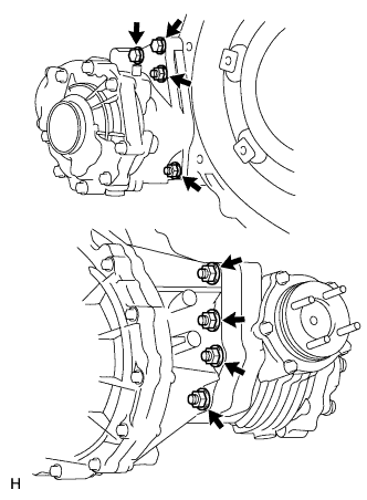
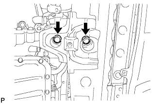
| 12. INSTALL TRANSFER ASSEMBLY |
except K111F:
Install the transfer to the transaxle with the 6 nuts and 2 bolts.- Torque:
- 69 N*m{700 kgf*cm, 51 ft.*lbf}
 |
for K111F:
Install the transfer to the transaxle with the 6 nuts and 2 bolts.- Torque:
- 69 N*m{700 kgf*cm, 51 ft.*lbf}
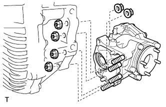 |
| 13. INSTALL DRIVE SHAFT BEARING BRACKET |
Install the bracket with the 3 bolts.
- Torque:
- 64 N*m{653 kgf*cm, 47 ft.*lbf}
 |
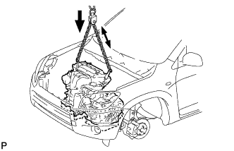
| 14. INSTALL ENGINE ASSEMBLY WITH TRANSAXLE |
Lift the engine assembly (with transaxle) with the chain block.
Slowly lower the engine assembly into the engine compartment.
- NOTICE:
- Make sure the engine is clear of all wiring, hoses and cables.
 |
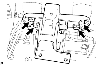
| 15. INSTALL ENGINE MOUNTING INSULATOR LH |
Install the engine mounting insulator LH with the 4 bolts.
- Torque:
- 95 N*m{969 kgf*cm, 70 ft.*lbf}
 |
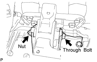
Install the engine mounting insulator LH with the through bolt and nut.
- HINT:
- Install the through bolt by tightening the nut.
- Torque:
- 56 N*m{571 kgf*cm, 41 ft.*lbf}
 |
| 16. INSTALL ENGINE MOUNTING INSULATOR RH |
Install the engine mounting insulator RH with the 2 bolts and 2 nuts.
- Torque:
- 95 N*m{969 kgf*cm, 70 ft.*lbf} for bolt
- 95 N*m{969 kgf*cm, 70 ft.*lbf} for nut A
- 52 N*m{530 kgf*cm, 38 ft.*lbf} for nut B
 |
| 17. REMOVE ENGINE HANGER |
Remove the No. 1 and No. 2 engine hangers.
 |
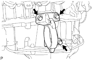
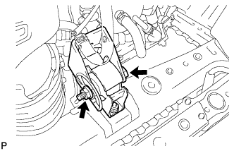
| 18. INSTALL ENGINE MOUNTING INSULATOR RR |
Install the engine mounting insulator RR with the 2 nuts and 2 bolts.
- Torque:
- 95 N*m{969 kgf*cm, 70 ft.*lbf}
 |
Install the through bolt which is used to secure the rear engine mounting insulator, into the engine mounting bracket RR.
- Torque:
- 95 N*m{969 kgf*cm, 70 ft.*lbf}
 |
| 19. INSTALL ENGINE MOUNTING INSULATOR FR |
Install the engine mounting insulator FR with the 2 bolts.
- Torque:
- 95 N*m{969 kgf*cm, 70 ft.*lbf}
 |
Install the through bolt and nut which are used to secure the engine mounting bracket FR.
- Torque:
- 145 N*m{1479 kgf*cm, 107 ft.*lbf}
 |
| 20. INSTALL PROPELLER SHAFT WITH CENTER BEARING SHAFT ASSEMBLY |
Install the propeller shaft with center bearing shaft assembly (RAV4_ACA30 RM00000226E001X.html).
| 21. INSTALL FRONT DRIVE SHAFT ASSEMBLY |
Install the front drive shaft (RAV4_ACA30 RM00000226O008X.html).
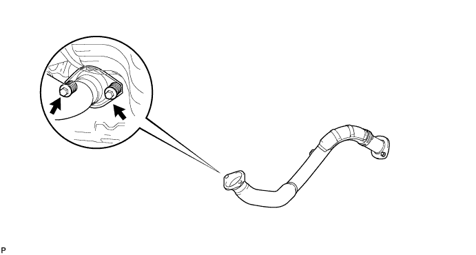
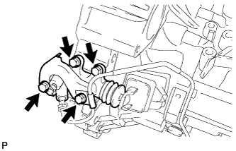
| 22. INSTALL FRONT EXHAUST PIPE ASSEMBLY |
Using a vernier caliper, measure the free length of the compression spring.
- Minimum length:
- 41.5 mm (1.634 in.)
 |
Install a new gasket by hand so that its surface is flush with the exhaust manifold.
- NOTICE:
- Make sure the gasket is facing the correct direction.
- Do not reuse the removed gasket.
- Do not push in the gasket while installing the front exhaust pipe.
 |
Install the front exhaust pipe with the 2 compression springs and 2 bolts.
- Torque:
- 43 N*m{438 kgf*cm, 32 ft.*lbf}
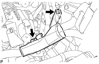
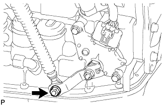
| 23. CONNECT ENGINE WIRE |
Install the ground cable with the bolt located near the starter.
- Torque:
- 13 N*m{133 kgf*cm, 10 ft.*lbf}
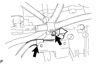 |
Connect the ground cable to the clamp located near the starter.
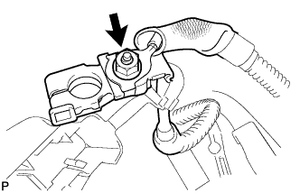
Connect the engine wire to the positive (+) battery terminal with the nut.
- Torque:
- 13 N*m{133 kgf*cm, 10 ft.*lbf}
 |
Connect the ground cable connector.
 |
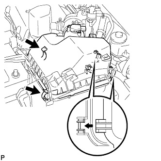
Connect the 2 engine wire connectors and install the nut.
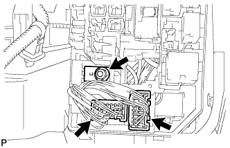 |
Install the engine room relay block cover.
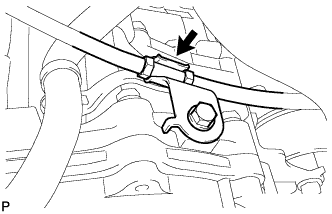
Attach the engine wire to the engine wire cover clamp.
 |
Install the engine wire cover with the bolt.
| 24. INSTALL ECM |
Install the ECM (RAV4_ACA30 RM0000017UM01GX_01_0001.html).
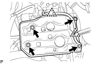
| 25. INSTALL COOLER COMPRESSOR ASSEMBLY (w/ Air Conditioning System) |
w/ Stud Bolt:
Install the cooler compressor with the 4 bolts.- Torque:
- 24.5 N*m{250 kgf*cm, 18 ft.*lbf}
- NOTICE:
- Tighten the bolts in the order shown in the illustration to install the cooler compressor.
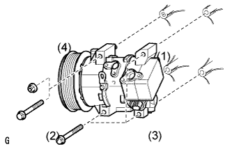 |
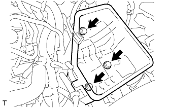
w/o Stud Bolt:
Install the cooler compressor with the 3 bolts and nut.- Torque:
- 24.5 N*m{250 kgf*cm, 18 ft.*lbf}
- NOTICE:
- Tighten the bolts in the order shown in the illustration to install the cooler compressor.
Connect the connector.
| 26. INSTALL GENERATOR ASSEMBLY |
Confirm that the wire harness of the crankshaft position sensor is secured to the wire harness clamp bracket through the back of the rib of the timing chain cover.
 |
Install the generator with the 2 bolts.
- Torque:
- 21 N*m{215 kgf*cm, 16 ft.*lbf}for bolt A
- 52 N*m{530 kgf*cm, 38 ft.*lbf}for bolt B
 |
Install the wire harness clamp.
 |
Install the wire harness clamp bracket with the bolt.
- Torque:
- 8.4 N*m{85 kgf*cm, 74 in.*lbf}
Connect the generator wire with the nut.
- Torque:
- 9.8 N*m{100 kgf*cm, 7 ft.*lbf}
Install the terminal cap.
Connect the generator connector.
| 27. INSTALL FAN & GENERATOR V BELT |
Using SST 19 mm socket wrench, loosen the V-ribbed belt tensioner arm clockwise, then install the fan and generator V belt.
- SST
- 09216-42010
- NOTICE:
- Be sure to connect SST and the tools so that they are in line during use.
- When retracting the tensioner, turn it clockwise slowly for 3 seconds or more. Do not apply force rapidly.
- After the tensioner is fully retracted, do not apply force any more than necessary.
 |
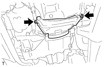
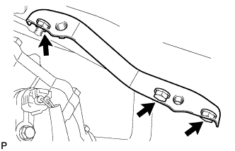
| 28. INSTALL FRONT SUSPENSION MEMBER REINFORCEMENT RH |
Install the reinforcement RH with the 4 bolts.
- Torque:
- 96 N*m{989 kgf*cm, 71 ft.*lbf}
| 29. INSTALL CLUTCH RELEASE CYLINDER ASSEMBLY (for Manual Transaxle) |
 |
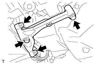
Install the clutch release cylinder with the 4 bolts.
- Torque:
- 12 N*m{120 kgf*cm, 9 ft.*lbf}
| 30. INSTALL TRANSAXLE CONTROL CABLE ASSEMBLY (for Manual Transaxle) |
 |
Install the control cable with the 2 bolts.
- Torque:
- 5.0 N*m{51 kgf*cm, 44 in.*lbf}
Connect the control cable to the control cable bracket, and install 2 new clips.
 |
Connect the control cable to the transaxle, and install the 2 washers and 2 clips.
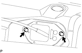
| 31. INSTALL TRANSAXLE CONTROL CABLE ASSEMBLY (for Automatic Transaxle) |
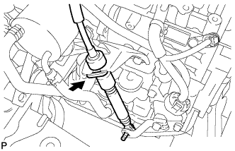
Install the control cable with the 2 bolts.
- Torque:
- 5.0 N*m{51 kgf*cm, 44 in.*lbf}
 |
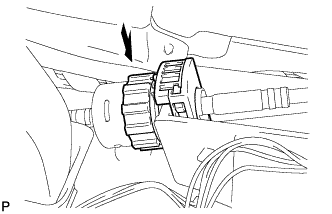
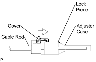
Turn the nut of the control cable and push in the lock.
 |
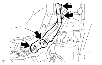
Install the control cable onto the shift lever retainer.
- NOTICE:
Install the cable with the protruding portion of the cable outer facing upward.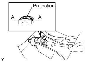
- After installing, check that the lock of the cable outer is protruding beyond portion A-A, as shown in the illustration.
 |
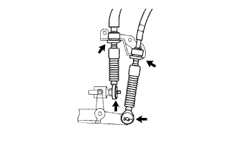
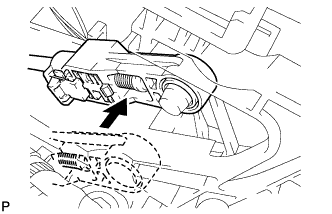
Connect the control cable to the shift lever.
- NOTICE:
- Connect the control cable so that the adjusting mechanism lock of the control cable is installed on the driver side of the vehicle.
 |
Fix the control cable onto the control cable bracket with the clip.
 |
Connect the control cable onto the control shaft lever with the nut.
- Torque:
- 12 N*m{122 kgf*cm, 9 ft.*lbf}
 |
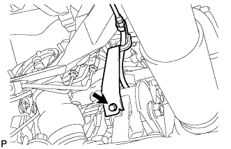
Connect the clamp of the control cable with the bolt.
- Torque:
- 12 N*m{122 kgf*cm, 9 ft.*lbf}
 |
Connect the control cable to the cable support.
 |
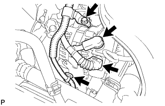
| 32. INSTALL INTAKE MANIFOLD INSULATOR |
Install the intake manifold insulator onto the cylinder block.
 |
| 33. INSTALL INTAKE MANIFOLD |
Install a new gasket into the intake manifold.
 |
Install the intake manifold with the 5 bolts and 2 nuts.
- Torque:
- 30 N*m{305 kgf*cm, 22 ft.*lbf}
 |
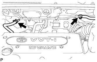
Fit the union to check valve hose into the vacuum hose clamp.
Install the wire harness clamp.
Connect the camshaft timing oil control valve connector.
Connect the union to check valve hose to the brake booster.
| 34. INSTALL FUEL DELIVERY PIPE SUB-ASSEMBLY |
Install 4 new insulators into the cylinder head.
 |
Install the 2 delivery pipe spacers onto the cylinder head.
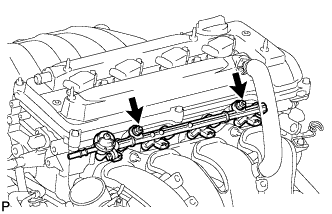
Install the fuel delivery pipe together with the 4 fuel injectors, then temporarily tighten the 2 bolts.
- NOTICE:
- Be careful not to drop the fuel injectors when installing the fuel delivery pipe.
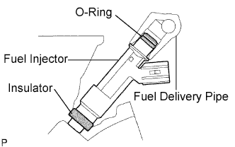 |
Check that the fuel injector rotates smoothly.
If the fuel injector does not rotate, replace the O-ring.
Tighten the 2 bolts to the specified torque.
- Torque:
- 20 N*m{204 kgf*cm, 15 ft.*lbf}
 |
Connect the 4 fuel injector connectors.
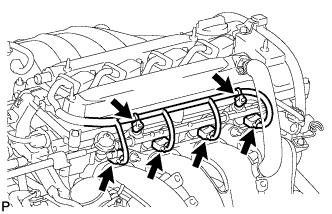 |
Install the 2 wire harness clamps.
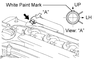
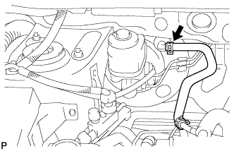
| 35. CONNECT NO. 2 VENTILATION HOSE |
Connect the ventilation hose to the ventilation valve.
- NOTICE:
- Make sure that the paint mark and hose clamp are at the correct angle when installing the hose.
 |
| 36. INSTALL THROTTLE BODY |
Install a new gasket onto the intake manifold.
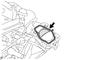 |
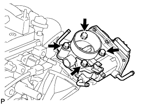
Install the throttle body and fuel pipe support with the 4 bolts.
- Torque:
- 30 N*m{306 kgf*cm, 22 ft.*lbf}
 |
Connect the fuel tube into the clamp.
 |
Connect the wire harness clamp.
Connect the throttle position sensor and control motor connector.
for Type A:
Connect the No. 1 throttle body hose to the throttle body.
Connect the No. 2 water by-pass hose to the throttle body.
Connect the water by-pass hose to the throttle body.
Connect the purge line hose to the throttle body.
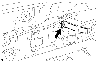
| 37. CONNECT FUEL MAIN TUBE |
Connect the fuel main tube.
Push the fuel tube connector until it makes a "click" sound.
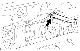
Install the fuel pipe clamp.
Install the fuel tube to the fuel hose clamp.
| 38. CONNECT HEATER WATER OUTLET HOSE |
Connect the heater water outlet hose to the heater unit.
 |
| 39. CONNECT HEATER WATER INLET HOSE |
Connect the heater water inlet hose to the heater unit.
 |
| 40. CONNECT UNION TO CONNECTOR TUBE HOSE (for LHD) |
Connect the 2 union to connector tube hoses to the booster vacuum tube.
 |
| 41. CONNECT UNION TO CONNECTOR TUBE HOSE (for RHD) |
Connect the union to connector tube hose to the booster vacuum tube.
 |
| 42. INSTALL BATTERY CARRIER BRACKET |
Install the battery carrier bracket with the nut and 2 bolts.
- Torque:
- 20 N*m{204 kgf*cm, 15 ft.*lbf}
 |
| 43. INSTALL BATTERY BRACKET REINFORCEMENT |
Install the battery bracket reinforcement with the 2 bolts.
- Torque:
- 20 N*m{204 kgf*cm, 15 ft.*lbf}
 |
| 44. INSTALL FRONT BATTERY CARRIER |
Install the front battery carrier with the 4 bolts.
- Torque:
- 20 N*m{204 kgf*cm, 15 ft.*lbf}
 |
Connect the 2 clamps of the engine wire.
| 45. INSTALL AIR CLEANER CASE |
Connect the air cleaner case to the No. 1 air cleaner inlet.
Install the case with the 3 bolts.
- Torque:
- 5.0 N*m{51 kgf*cm, 44 in.*lbf}
 |
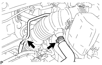
| 46. INSTALL AIR CLEANER CAP |
Install the air cleaner filter element onto the air cleaner case.
Insert the hinge part of the air cleaner cap into the air cleaner case, then hang the 2 hook clamps.
 |
Align the matchmarks of the No. 1 air cleaner hose and throttle body, and then connect the air cleaner hose No. 1 to the throttle body and unfasten the No. 1 air cleaner hose clamp.
- NOTICE:
- Make sure that the hose clamp is at the correct angle.
 |
Connect the purge line hose to the clamp.
 |
Connect the No. 2 ventilation hose to the air cleaner hose.
Connect the 4 wire harness clamps.
 |
Connect the mass air flow meter connector.
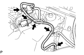
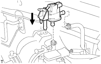
| 47. INSTALL PURGE VSV |
Install the purge VSV onto the air cleaner hose.
 |
Connect the 2 purge line hoses to the purge VSV.
 |
Connect the wire harness clamp.
Connect the purge VSV connector.
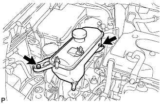
| 48. INSTALL RADIATOR RESERVOIR TANK |
Install the radiator reservoir with the 2 bolts.
- Torque:
- 5.0 N*m{51 kgf*cm, 44 in.*lbf}
 |
| 49. INSTALL RADIATOR ASSEMBLY |
Install the radiator (RAV4_ACA30 RM000001X9E00MX.html).
| 50. INSTALL BATTERY TRAY |
| 51. INSTALL BATTERY |
| 52. INSTALL BATTERY CLAMP SUB-ASSEMBLY |
Install the battery clamp with the bolt and nut.
- Torque:
- 4.9 N*m{50 kgf*cm, 43 in.*lbf} for nut
- 17 N*m{168 kgf*cm, 12 ft.*lbf} for bolt
| 53. CONNECT CABLE TO NEGATIVE BATTERY TERMINAL |
| 54. ADD MANUAL TRANSAXLE OIL |
| 55. ADD AUTOMATIC TRANSAXLE FLUID |
- Fluid type:
- Toyota Genuine ATF WS
| 56. CHECK FOR FUEL LEAKS |
 |
Make sure that there are no fuel leaks after performing maintenance on the fuel system.
Connect the intelligent tester to the DLC3.
Turn the ignition switch on (IG), and push the intelligent tester main switch ON.
- NOTICE:
- Do not start the engine.
Select the Active Test mode on the intelligent tester.
- HINT:
- Refer to the intelligent tester operator's manual for further details.
Check that there are no leaks from the fuel system.
Turn the ignition switch off.
Disconnect the intelligent tester from the DLC3.
| 57. ADD ENGINE COOLANT |
Tighten the radiator drain cock plug by hand.
Tighten the cylinder block drain cock plug.
- Torque:
- 12.7 N*m{130 kgf*cm, 10 ft.*lbf}
Add TOYOTA Super Long Life Coolant (SLLC) to the radiator reservoir filler opening.
Continue adding TOYOTA SLLC until it is filled to the B line at the base of the reservoir's filler neck.
- HINT:
- The B line is the lower edge of the inner wall of the filler neck.
- Standard capacity:
Item Specified Condition A/T 6.4 liters (6.8 US qts, 5.6 Imp. qts) M/T 6.3 liters (6.7 US qts, 5.5 Imp. qts)
- HINT:
- TOYOTA vehicles are filled with TOYOTA SLLC at the factory. In order to avoid damage to the engine cooling system and other technical problems, only use TOYOTA SLLC or similar high quality ethylene glycol based non-silicate, non-amine, non-nitrite, non-borate coolant with long-life hybrid organic acid technology (coolant with long-life hybrid organic acid technology consists of a combination of low phosphates and organic acids).
- NOTICE:
- Never use water as a substitute for engine coolant.
 |
Press the No. 1 and No. 2 radiator hoses several times by hand, and then check the level of the coolant. If the coolant level drops below the B line, add TOYOTA SLLC to the B line.
Install the radiator reservoir cap.
Start the engine and warm it up until the cooling fan operates. While the cooling fan operates, circulate the coolant for several minutes.
Set the air conditioning as follows while warming up the engine.
Item Specified Condition Manual Air Conditioning System Fan speed: Any setting except OFF Temperature: Toward WARM
Air conditioning switch: OFFAutomatic Air Conditioning System Temperature: Toward MAX
Air conditioning switch: OFFMaintain the engine speed at 2,000 to 2,500 rpm and warm up the engine until the cooling fan operates.
- NOTICE:
- Make sure that the radiator reservoir still has some coolant in it.
- Pay attention to the needle of the water temperature meter. Make sure that the needle does not show an abnormally high temperature.
- If there is not enough coolant, the engine may burn out or overheat.
- Immediately after starting the engine, if the radiator reservoir does not have any coolant, perform the following: 1) stop the engine, 2) wait until the coolant has cooled down, and 3) add coolant until the coolant is filled to the B line.
- Run the engine at 2,000 rpm until the coolant level has stabilized.
Press the No. 1 and No. 2 radiator hoses several times by hand to bleed air.
- CAUTION:
When pressing the radiator hoses:- Wear protective gloves.
- Be careful as the radiator hoses are hot.
- Keep your hands away from the radiator fan.
Stop the engine and wait until the coolant cools down to ambient temperature.
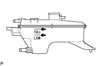
Check that the coolant level is between the FULL and LOW line.
If the coolant level is below the LOW line, repeat all of the procedures above.
If the coolant level is above the FULL line, drain coolant so that the coolant level is between the FULL and LOW line.
 |
| 58. CHECK FOR ENGINE COOLANT LEAKS |
Check for engine coolant leaks (RAV4_ACA30 RM0000017W200QX_01_0001.html).
| 59. CHECK FOR MANUAL TRANSAXLE OIL LEAKS |
| 60. CHECK FOR AUTOMATIC TRANSAXLE FLUID LEAKS |
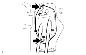
| 61. INSPECT SHIFT LEVER POSITION |
Shift the shift lever to the N position.
Slide the adjuster case cover in the direction shown in the illustration and pull out the lock piece.
 |
Gently pull the cable rod toward the rear of the vehicle by hand to pull the cable taut.
Press the lock piece into the adjuster case and lock it.
 |
Slide the cover in the direction shown in the illustration.
- NOTICE:
- Slide the cover past the protrusion of the lock piece.
 |
Inspect the operation after the adjustment.
| 62. ADJUST SHIFT LEVER POSITION |
Adjust the shift lever position (RAV4_ACA30 RM000001SUE00UX.html).
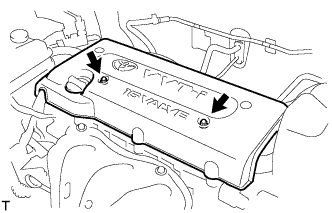
| 63. INSTALL NO. 1 ENGINE COVER |
Install the engine cover with the 2 nuts.
- Torque:
- 7.0 N*m{71 kgf*cm, 62 in.*lbf}
 |
| 64. INSTALL FRONT FENDER APRON RH |
| 65. INSTALL NO. 2 ENGINE UNDER COVER |
| 66. INSTALL NO. 1 ENGINE UNDER COVER |
| 67. INSTALL FRONT WHEEL |
| 68. INSTALL RADIATOR SUPPORT OPENING COVER |
| 69. INSTALL HOOD SUB-ASSEMBLY |
Install the hood (RAV4_ACA30 RM00000161X00KX_01_0003.html).
Adjust the hood (RAV4_ACA30 RM00000138K00WX_02_0001.html).
| 70. INSPECT AND ADJUST FROM WHEEL ALIGNMENT |
Inspect and adjust the front wheel alignment (RAV4_ACA30 RM00000227W003X.html).
| 71. PERFORM REGISTRATION |
w/ Cruise Control:
When replacing the engine assembly, perform vehicle stability control system recognition in ECM (RAV4_ACA30 RM00000226C001X.html).
| 72. RESET MEMORY (for Automatic Transaxle) |
When replacing the engine assembly, perform the RESET MEMORY procedure (A/T initialization) (RAV4_ACA30 RM000000W7F0AKX.html).