Combustion Type Power Heater System Power Heater Fuel Pump Circuit
Heater. Lexus Is250, Is220D. Gse20 Ale20
DESCRIPTION
WIRING DIAGRAM
INSPECTION PROCEDURE
CHECK HARNESS AND CONNECTOR (COMBUSTION HEATER ASSEMBLY - HEATER FUEL PUMP)
CHECK HARNESS AND CONNECTOR (HEATER FUEL PUMP - BODY GROUND)
INSPECT HEATER FUEL PUMP
INSPECT POWER HEATER ECU (COMBUSTION HEATER ASSEMBLY)
COMBUSTION TYPE POWER HEATER SYSTEM - Power Heater Fuel Pump Circuit |
DESCRIPTION
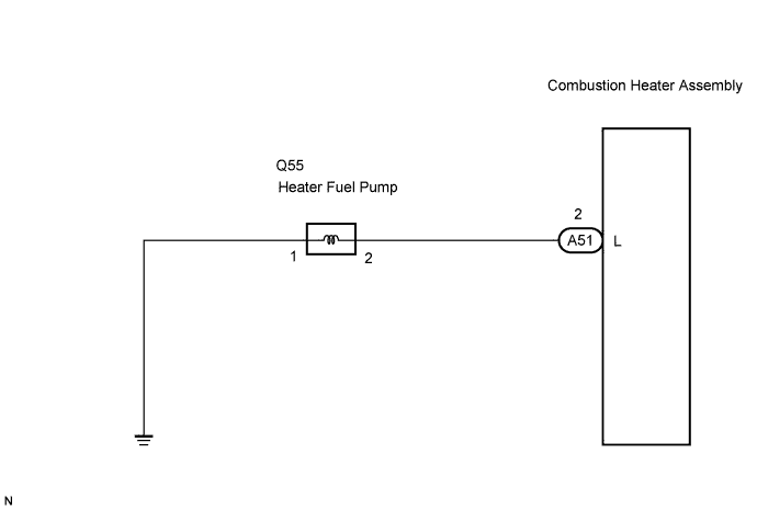
When the power heater switch is turned on, the heater fuel pump receives a drive voltage from the power heater ECU (combustion heater assembly). The heater fuel pump provides the combustion heater assembly with fuel necessary for combustion, allowing the combustion heater assembly to operate.
WIRING DIAGRAM
INSPECTION PROCEDURE
| 1.CHECK HARNESS AND CONNECTOR (COMBUSTION HEATER ASSEMBLY - HEATER FUEL PUMP) |
Disconnect the connector from the power heater ECU (combustion heater assembly).
Disconnect the connector from the heater fuel pump.
Measure the resistance according to the value(s) in the table below.
- Standard resistance:
Tester connection
(Symbols)
| Condition
| Specified condition
|
A51-2 (L) - Q55-2
| Always
| Below 1 Ω
|
A51-2 (L) - Body ground
| Always
| 10 kΩ or higher
|
| | REPAIR OR REPLACE HARNESS OR CONNECTOR |
|
|
| 2.CHECK HARNESS AND CONNECTOR (HEATER FUEL PUMP - BODY GROUND) |
Measure the resistance according to the value(s) in the table below.
- Standard resistance:
Tester connection
| Condition
| Specified condition
|
Q55-1 - Body ground
| Always
| Below 1 Ω
|
| | REPAIR OR REPLACE HARNESS OR CONNECTOR |
|
|
| 3.INSPECT HEATER FUEL PUMP |
Measure the resistance according to the value(s) in the table below.
- Standard resistance:
Tester connection
| Condition
| Specified condition
|
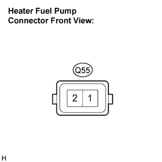
Q55-2 - Q55-1
| Always
| 9 to 12 Ω
|
Inspect heater fuel pump operation.
Connect the positive (+) lead from the battery to terminal 2 and the negative (-) lead to terminal 1, and check the pressure of the hose by hand.
- NOTICE:
- This inspection must be done quickly (within 10 seconds) to prevent damage to the heater fuel pump.
- OK:
- The pressure is applied to the hose.
| 4.INSPECT POWER HEATER ECU (COMBUSTION HEATER ASSEMBLY) |
Reconnect the connector to the power heater ECU (combustion heater assembly).
Measure the voltage according to the value(s) in the table below.
- Standard voltage:
Tester connection
| Condition
| Specified condition
|
Q55-2 - Body ground
| Engine switch: START
Power heater switch: ON
| 10 to 14 V
|
Q55-2 - Body ground
| Engine switch: START
Power heater switch: OFF
| Below 1 V
|
| | REPLACE POWER HEATER ECU (COMBUSTION HEATER ASSEMBLY) |
|
|
| OK |
|
|
|
| PROCEED TO NEXT CIRCUIT INSPECTION SHOWN IN PROBLEM SYMPTOMS TABLE |
|