Combustion Type Power Heater System Power Heater Switch Circuit
Heater. Lexus Is250, Is220D. Gse20 Ale20
DESCRIPTION
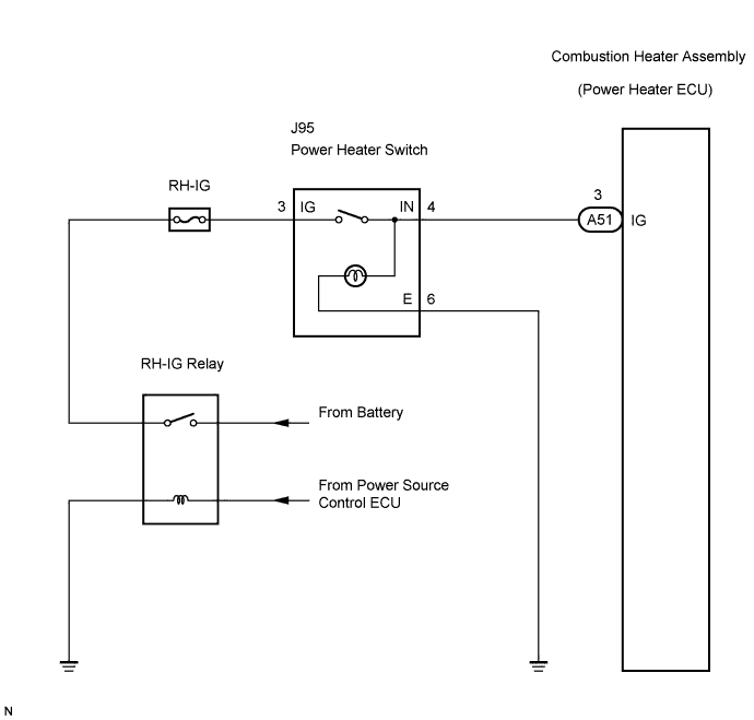
WIRING DIAGRAM
INSPECTION PROCEDURE
INSPECT POWER HEATER SWITCH
CHECK HARNESS AND CONNECTOR (POWER HEATER ECU (COMBUSTION HEATER ASSEMBLY) - BATTERY)
CHECK HARNESS AND CONNECTOR (POWER HEATER SWITCH - BODY GROUND)
COMBUSTION TYPE POWER HEATER SYSTEM - Power Heater Switch Circuit |
DESCRIPTION
When the power heater switch is turned on, the power heater ECU (combustion heater assembly) sends a drive signal to the heater fuel pump. The combustion heater assembly then receives fuel necessary for combustion and starts operating.
WIRING DIAGRAM
INSPECTION PROCEDURE
| 1.INSPECT POWER HEATER SWITCH |
Measure the resistance.
Remove the power heater switch.
Disconnect the connector from the power heater switch.
Measure the resistance according to the value(s) in the table below.
- Standard resistance:
Tester connection
(Symbols)
| Condition
| Specified condition
|
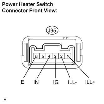
J95-3 (IG) - J95-4 (IN)
| Power heater switch: ON
| Below 1 Ω
|
J95-3 (IG) - J95-4 (IN)
| Power heater switch: OFF
| 10 kΩ or higher
|
Check that the power heater switch operation indicator comes on.
Connect the positive (+) lead from the battery to terminal 4 (IN) and the negative (-) lead to terminal 6 (E), and check that the operation indicator comes on.
- OK:
- Indicator comes on.
Check that the power heater switch illumination comes on.
Connect the positive (+) lead from the battery to terminal 1 (ILL+) and the negative (-) lead to terminal 2 (ILL-), and check that the switch illumination comes on.
- OK:
- Illumination comes on.
| | REPLACE POWER HEATER SWITCH |
|
|
| 2.CHECK HARNESS AND CONNECTOR (POWER HEATER ECU (COMBUSTION HEATER ASSEMBLY) - BATTERY) |
Remove the power heater ECU (combustion heater assembly).
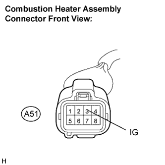
Disconnect the connector from the power heater ECU (combustion heater assembly).
Measure the voltage according to the value(s) in the table below.
- Standard voltage:
Tester connection
(Symbols)
| Condition
| Specified condition
|
A51-3 (IG) - Body ground
| Engine switch: on (IG)
Power heater switch: ON
| 10 to 14 V
|
A51-3 (IG) - Body ground
| Engine switch: on (IG)
Power heater switch: OFF
| Below 1 V
|
| | REPAIR OR REPLACE HARNESS OR CONNECTOR |
|
|
| 3.CHECK HARNESS AND CONNECTOR (POWER HEATER SWITCH - BODY GROUND) |
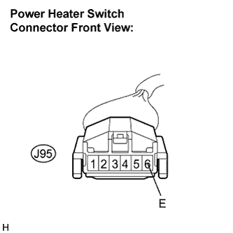
Disconnect the connector from the power heater switch.
Measure the resistance according to the value(s) in the table below.
- Standard resistance:
Tester connection
(Symbols)
| Condition
| Specified condition
|
J95-6 (E) - Body ground
| Always
| Below 1 Ω
|
| | REPAIR OR REPLACE HARNESS OR CONNECTOR |
|
|
| OK |
|
|
|
| PROCEED TO NEXT CIRCUIT INSPECTION SHOWN IN PROBLEM SYMPTOMS TABLE |
|