Dtc B1242 Wireless Door Lock Tuner Circuit Malfunction
DESCRIPTION
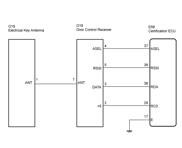
WIRING DIAGRAM
INSPECTION PROCEDURE
CHECK HARNESS AND CONNECTOR (CERTIFICATION ECU - DOOR CONTROL RECEIVER)
INSPECT CERTIFICATION ECU
REPLACE DOOR CONTROL RECEIVER
DTC B1242 Wireless Door Lock Tuner Circuit Malfunction |
DESCRIPTION
- The electrical key antenna is used to receive electric waves relating to the entry functions of the smart access system with push-button start. The certification ECU decodes the requested smart access system with push-button start operation by identifying a key code based on electric waves received via the electrical key antenna and the door control receiver.
- The door control receiver receives a signal from the wireless door control transmitter and sends signals to the main body ECU RH through the certification ECU.
- The certification ECU then sends a command, according to the requested operation, to each ECU. (e.g. If door lock operation is requested, the ECU sends a door lock command to the main body ECU RH.)
DTC No.
| DTC Detection Condition
| Trouble Area
|
B1242
| The certification ECU detects that there is a short in the circuit between terminals RSSI, or between terminals DATA and RDA.
| - Door Control Receiver
- Wire harness
- Certification ECU
|
WIRING DIAGRAM
INSPECTION PROCEDURE
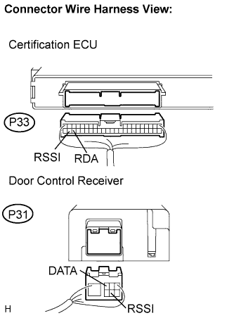
| 1.CHECK HARNESS AND CONNECTOR (CERTIFICATION ECU - DOOR CONTROL RECEIVER) |
Disconnect the P33 certification ECU connector and P31 door control receiver connector.
Measure the resistance according to the value(s) in the table below.
- Standard resistance:
Symbol
(Tester Connection)
| Condition
| Specified Condition
|
RSSI (P33-39) - RSSI (P31-5)
| Always
| Below 1 Ω
|
RDA (P33-38) - DATA (P31-3)
| Always
| Below 1 Ω
|
RSSI (P33-39) - RDA (P33-38)
| Always
| 10 kΩ or higher
|
RSSI (P33-39) - Body ground
| Always
| 10 kΩ or higher
|
RDA (P33-38) - Body ground
| Always
| 10 kΩ or higher
|
| | REPAIR OR REPLACE HARNESS OR CONNECTOR |
|
|
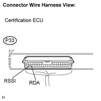
| 2.INSPECT CERTIFICATION ECU |
Reconnect the P33 ECU connector.
Measure the voltage according to the value(s) in the table below.
- Standard voltage:
Symbol
(Tester Connection)
| Condition
| Specified Condition
|
RSSI (P33-39) - E (P33-17)
| Engine switch OFF, all doors closed, the electrical key is not the actuation area
| Below 1 V
|
Engine switch OFF, all doors closed, the electrical key is the actuation area
| 4.6 to 5.4 V
|
RDA (P33-38) - E (P33-17)
| Engine switch OFF, all doors closed and transmitter switch not pressed
| Below 1 V
|
Engine switch OFF, all doors closed and transmitter switch pressed
| 4.6 to 5.4 V
|
| | REPLACE CERTIFICATION ECU |
|
|
| 3.REPLACE DOOR CONTROL RECEIVER |
Replace the door control receiver with normal one
Perform the registration procedure.
- OK:
- The system returns to normal operation.
| | REPLACE CERTIFICATION ECU |
|
|