Dtc C1305/21 Solenoid Identification Circuit
Brake. Lexus Is250, Is220D. Gse20 Ale20
DESCRIPTION
WIRING DIAGRAM
INSPECTION PROCEDURE
CHECK HARNESS AND CONNECTOR (SKID CONTROL ECU - BRAKE ACTUATOR ASSEMBLY)
INSPECT SKID CONTROL ECU (IDENTIFICATION OUTPUT)
RECONFIRM DTC
DTC C1305/21 Solenoid Identification Circuit |
DESCRIPTION
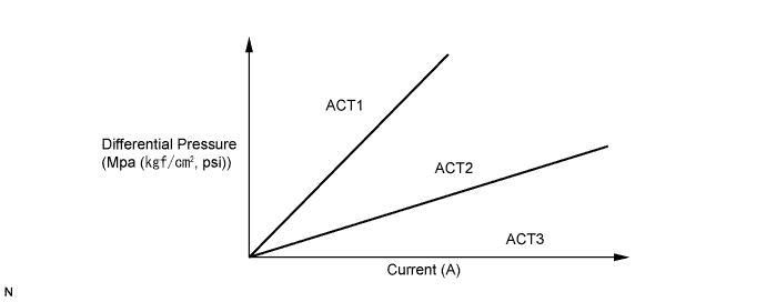
The skid control ECU receives solenoid identification signals from terminals SSEL and SEL2. The ECU specifies control characteristics of the brake actuator by monitoring the difference in the holding solenoid (FRA, FLA, RRA and RLA) current, which is caused by characteristics of each actuator.DTC No.
| DTC Detection Condition
| Trouble Area
|
C1305/21
| Immediately after the engine is started, an open or short in the solenoid characteristics identification circuit continues for 0.21 seconds or more.
| - Internal solenoid identification circuit of the brake actuator assembly
- Skid control ECU
|
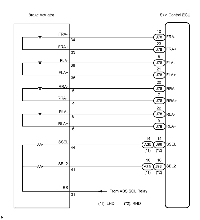
WIRING DIAGRAM
INSPECTION PROCEDURE
- NOTICE:
- When replacing the skid control ECU, perform zero point calibration and store system information (Click here).
| 1.CHECK HARNESS AND CONNECTOR (SKID CONTROL ECU - BRAKE ACTUATOR ASSEMBLY) |
Disconnect the skid control ECU connector and the brake actuator connector.
Measure the resistance according to the value(s) in the table below.
- Standard resistance:
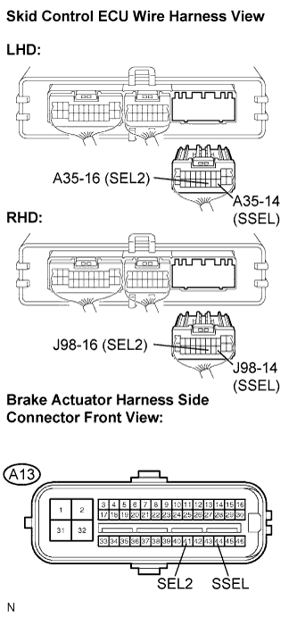
- LHD:
Tester Connection
| Condition
| Specified Condition
|
A35-14 (SSEL) - A13-44 (SSEL)
| Always
| Below 1 Ω
|
A35-14 (SSEL) - Body ground
| Always
| 10 kΩ or higher
|
A35-16 (SEL2) - A13-41 (SEL2)
| Always
| Below 1 Ω
|
A35-16 (SEL2) - Body ground
| Always
| 10 kΩ or higher
|
- RHD:
Tester Connection
| Condition
| Specified Condition
|
J98-14 (SSEL) - A13-44 (SSEL)
| Always
| Below 1 Ω
|
J98-14 (SSEL) - Body ground
| Always
| 10 kΩ or higher
|
J98-16 (SEL2) - A13-41 (SEL2)
| Always
| Below 1 Ω
|
J98-16 (SEL2) - Body ground
| Always
| 10 kΩ or higher
|
| | REPAIR OR REPLACE HARNESS OR CONNECTOR |
|
|
| 2.INSPECT SKID CONTROL ECU (IDENTIFICATION OUTPUT) |
Reconnect the skid control ECU connector and the brake actuator connector.
Start the engine.
Measure the voltage according to the value(s) in the table below.
- Standard voltage:
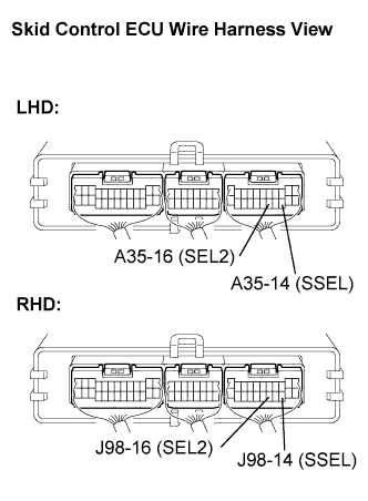
- LHD:
Tester Connection
| Condition
| Specified Condition
|
A35-14 (SSEL) - Body ground
| Low (Normal)
| 0 V
|
A35-14 (SSEL) - Body ground
| Middle
| 3.7 to 8.26 V
|
A35-14 (SSEL) - Body ground
| High
| 7.8 to 14 V
|
A35-16 (SEL2) - Body ground
| Low (Normal)
| 0 V
|
A35-16 (SEL2) - Body ground
| Middle
| 3.7 to 8.26 V
|
A35-16 (SEL2) - Body ground
| High
| 7.8 to 14 V
|
- RHD:
Tester Connection
| Condition
| Specified Condition
|
J98-14 (SSEL) - Body ground
| Low (Normal)
| 0 V
|
J98-14 (SSEL) - Body ground
| Middle
| 3.7 to 8.26 V
|
J98-14 (SSEL) - Body ground
| High
| 7.8 to 14 V
|
J98-16 (SEL2) - Body ground
| Low (Normal)
| 0 V
|
J98-16 (SEL2) - Body ground
| Middle
| 3.7 to 8.26 V
|
J98-16 (SEL2) - Body ground
| High
| 7.8 to 14 V
|
- OK:
- Input voltage of SSEL and SEL2 is the same under all conditions.
| | REPLACE BRAKE ACTUATOR ASSEMBLY |
|
|
Turn the engine switch off.
Clear the DTC (Click here).
Drive the vehicle at the speed of 15 mph (24 km/h) or more.
Check if the same DTC is recorded (Click here).
- Result:
Condition
| Proceed to
|
DTC (C1305/21) is not output
| A
|
DTC (C1305/21) is output
| B
|
- HINT:
- If the normal system code is output (the trouble code is not output), slightly jiggle the connectors, wire harness, and fuses of the skid control ECU and brake actuator assembly. Make sure that no DTCs are output.
- If any DTCs are output while jiggling a connector or wire harness of the skid control ECU and brake actuator assembly, inspect and repair the connector or wire harness.
| A |
|
|
|
| USE SIMULATION METHOD TO CHECK |
|