Theft Deterrent System (W/ Intrusion Sensor) Security Horn Circuit
DESCRIPTION
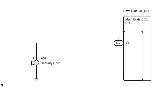
WIRING DIAGRAM
INSPECTION PROCEDURE
INSPECT SECURITY HORN ASSEMBLY
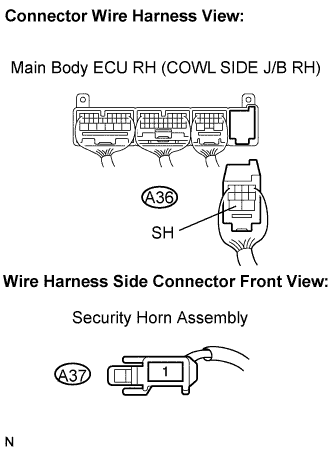
CHECK HARNESS AND CONNECTOR (MAIN BODY ECU RH (COWL SIDE J/B RH) - SECURITY HORN ASSEMBLY)
THEFT DETERRENT SYSTEM (w/ Intrusion Sensor) - Security Horn Circuit |
DESCRIPTION
When the theft deterrent system is operating, the relay in the main body ECU RH turns on and off, causing the security horn to sound.
WIRING DIAGRAM
INSPECTION PROCEDURE
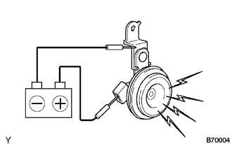
| 1.INSPECT SECURITY HORN ASSEMBLY |
Remove the security horn assembly.
Check operation of the horn.
- Standard:
Measurement Condition
| Specified Condition
|
Battery positive (+) → Terminal 1
| Horn sounds
|
Battery negative (-) → Horn body
|
| | REPAIR OR REPLACE SECURITY HORN ASSEMBLY |
|
|
| 2.CHECK HARNESS AND CONNECTOR (MAIN BODY ECU RH (COWL SIDE J/B RH) - SECURITY HORN ASSEMBLY) |
Disconnect the A36 ECU connector and the A37 horn connector.
Measure the resistance according to the value(s) in the table below.
- Standard resistance:
Symbol (Terminal Connection)
| Specified Condition
|
SH (A36-1) - (A37-1)
| Below 1 Ω
|
SH (A36-1) or (A37-1) - Body ground
| 10 kΩ or higher
|
| | REPAIR OR REPLACE HARNESS OR CONNECTOR |
|
|
| OK |
|
|
|
| PROCEED TO NEXT CIRCUIT INSPECTION SHOWN IN PROBLEM SYMPTOMS TABLE |
|